International Journal of Radiology and Radiation Oncology
CT Scanner Based Virtual Simulation of Radiotherapy Treatment by the PICTOR 3D® System Does not Increase Efficacy in Daily Routine Radiation Therapy
Mirko Nitsche1,2, Nils Temme1, Ulrich Martin Carl1 and Robert Michael Hermann3,4*
2Klinik für Strahlentherapie, Karl-Lennert-Krebscentrum, Universität Kiel, Germany
3Zentrum für Strahlentherapie und Radioonkologie, Westerstede, Germany
4Abteilung Strahlentherapie und Spezielle Onkologie, Medizinische Hochschule Hannover, Germany
Cite this as
Nitsche M, Temme N, Carl UM, Hermann RM (2015) CT Scanner Based Virtual Simulation of Radiotherapy Treatment by the PICTOR 3D® System Does not Increase Efficacy in Daily Routine Radiation Therapy Int J Radiol Radiat Oncol 1(1): 004-006. DOI: 10.17352/ijrro.000003Exact reproduction of patient position is crucial in radiotherapy. We evaluated the reproducibility of a CT based treatment simulation with the PICTOR 3D® system (LAP, Lüneburg, Germany) and examined its influence on workflow in daily routine.
Ulterior motive to introduce such a simulation system is to save time at the radiation treatment machine (LINAC). Normally, treatment simulations are directly done at the LINAC (so called „virtual simulation“). However, this procedure is time consuming, and opportunity costs are much higher for the LINAC than for the treatment planning CT scanner. This explains the efforts to switch the simulation process from the LINAC to the planning CT.
In 31 patients the isocenter marks were drawn at the planning CT with laser projections, and afterwards controlled at the LINAC based imaging system. The mean offsets between both simulations were 2.7 ± 2.4 mm in lateral, 2.3 ± 2.2 mm in longitudinal, and 1.9 ± 1.7 mm in sagittal direction. In 14 patients (45%) the deviation was ≥5mm in at least one direction. In both separately evaluated anatomical regions (thorax, pelvis) and all age groups significant offsets were seen. The time span for a virtual simulation with the PICTOR 3D® system was 18 ± 2 min (ranging from 15 to 23min).
The LINAC based virtual simulation cannot be replaced by the CT based simulation with PICTOR 3D®, as the latter is lacking an option to verify the laser projected isocenter at the CT scanner. The daily workflow is not improved by this system, it is dispensable in daily clinical routine.
Introduction
In radiotherapy exact positioning of the patient for treatment delivery is crucial. In daily routine procedures, the position of the isocenter (the pivot of the linear accelerator [LINAC]) is marked on the skin of the patient with a water proof pen by means of three laser projections. These lasers represent the longitudinal, the lateral and the sagittal patient position in reference to the isocenter.
Traditionally, these skin marks are drawn with help of a treatment simulator. It consists of an X-ray device and simulates the treatment field borders of the LINAC with X-ray and light fields.
As modern treatment machines are routinely equipped with additional imaging features (megavoltage or kilo voltage imaging, even cone beam CT scans can be acquired) a treatment simulator is dispensable.
A simple way of treatment simulation without a special simulation machine is called “virtual simulation” and has been extensively described before [1]. In short, after completion of treatment planning, the patient is directly placed at the LINAC, and his actual position is registered by the LINAC based imaging units. This patient position (especially bone marks) is matched to the planned patient position, and the couch is adjusted for the calculated vector. Again the patient position is registered, and the bone marks of the actual position are matched with the planned position. In case of exact accordance the skin marks are drawn for daily positioning during treatment.
However, these procedures occupy treatment time of the LINAC. As all modern 3D treatment planning is based on CT scans, nearly all radiation departments are equipped with a CT scanner. This is why the idea to use a CT scanner for treatment simulation to increase efficacy of workflow is convincing.
We evaluated the reproducibility of a CT based treatment simulation with the PICTOR 3D® system (LAP, Lüneburg, Germany) and evaluated its influence on daily workflow in our clinics.
Methods
Planning CT scans were acquired with a Siemens Sensation CT-scanner (Erlangen, Germany). The isocenter was defined and a treatment plan was calculated with the Treatment Planning Systems [TPS] XiO (Elekta/CMS, Version 4.50) and Pinnacle3 (Philips, Version 9.6).
For virtual simulation at the CT-scanner we used the PICTOR 3D® system. It includes a laser system which uses a multi projection format that defines isocenters and the field shape (the multi leaf collimator contours) along with a 3D patient view. The PICTOR 3D laser projectors were mounted in the plane perpendicular to the longitudinal axis of the imaging device’s couch. The treatment plan containing isocenter and MLC positions was transferred from the TPS system to the PICTOR-control-software CARINAsim®. The software calculated the coordinates of the intersecting therapy field, based on the target volumes established by the TPS, and the patient surface. Both, the isocenter and the MLC-shape of the desired treatment beam, were projected on the patient surface and marked by the technical assistants.
Our department is equipped with two LINACs (one Siemens Artiste and one Siemens Oncor, Germany). Both Linacs have a 6MV on board-imaging-system for patient positioning. Before the patient received the first irradiation at the LINAC the isocenter was verified by another virtual simulation using the on board imaging-system of the LINACs. The differences between the virtual simulations based on PICTOR 3D® and on the LINAC were documented.
Patient immobilization was defined at the planning CT. No changes in immobilization techniques were permitted between planning CT and simulation or treatment at the LINAC to minimize any avoidable inaccuracies. All patient immobilization materials were provided by Unger (Mülheim-Kärlich, Germany). Patients and immobilization cushions and accessories were placed on carbon fibre laminate base plates. For cerebral radiotherapy patients were positioned in a thermoplastic head mask, that was individually moulded on each patient. Breast cancer and lung cancer patients were treated in supine position with the arms positioned over the head by use of armrests and a special breast board. Patients with rectal, anal and prostate cancer were also treated in supine position with hand grips, knee cushions and feet positioning.
Mean values (as the usual average) and standard deviations (as the square root of variance) were calculated. Subgroup analyses (anatomical region, age) were done in order to define a collective at highest risk for inaccuracies. Deviations in each direction were compared according to anatomical region (thorax vs. pelvis) and patient age (< 67 vs. ≥ 67 years to generate two patient groups of similar size) with Mann-Whitney-U (MWU) test (Statistica 10.0, StatSoft, Hamburg, Germany).
Results
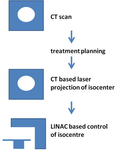
In thirty patients the isocenter marks were drawn at the planning CT with laser projections of the PICTOR 3D® system, and afterwards controlled at the LINAC based imaging system (Artiste, Siemens, Germany) before initiation of the irradiation (Figure 1). The mean age of the examined patients was 67 ± 11.6 years (ranging from38 to 82 years).
Seventeen patients were irradiated for breast cancer (n = 13 after breast conserving surgery, n = 4 after mastectomy). Out of these patients, three were treated with the supraclavicular lymphatic region. One patient received palliative radiotherapy for axillary metastases, another was treated for lung cancer. Two patients received radiotherapy for prostate cancer (one prostate only, one with pelvine lymphatics). One patient was treated for rectal, another for anal cancer. Five patients received radiotherapy for bone metastases (3 in the lumbar spine, 2 in the pelvic region). Two patients got cerebral radiotherapy. One patient received low dose radiation for bursitis trochanterica.
Reproducibility of CT based simulation to LINAC based Imaging
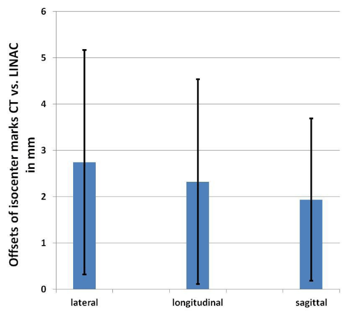
The mean offsets between CT drawn isocenters and the actual isocenters were 2.7 ± 2.4 mm in lateral, 2.3 ± 2.2 mm in longitudinal, and 1.9 ± 1.7 mm in sagittal direction (Figure 2). In 14 patients (45%) the deviation exceeded 5 mm in at least one direction. Only in 4 patients (13%) the deviation was 1mm or less in all directions.
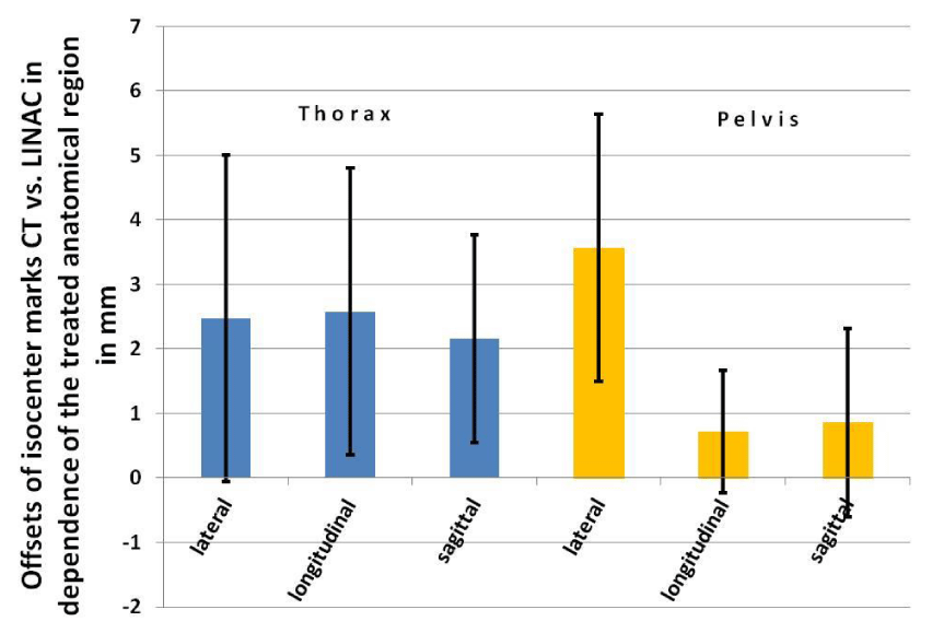
We evaluated the offsets according to the irradiated anatomical regions, too. Nineteen patients were treated in the thoracic region, n = 7 in the pelvis. The mean offsets in the thoracic region were 2.4 ± 2.5 mm in lateral, 2.6 ± 2.2 mm in longitudinal, and 2.2 ± 1.6 mm in sagittal direction (Figure 3). The deviations in the pelvis were in the longitudinal und sagittal directions somewhat smaller (lateral 3.6 ± 2.1 mm, longitudinal 0.7 ± 1.0 mm, sagittal 0.9 ± 1.5 mm), however, they did not reach statistical significance in MWU-test.
We also investigated the influence of patient age on the measured offsets. Sixteen patients were 67 years or older, fifteen were younger. The mean offset values were very similar without statistical significance with 2.9 ± 2.6 mm vs. 2.5 ± 2.3 mm in the lateral, 2.4 ± 2.5 mm vs. 2.3 ± 1.9 mm in the longitudinal, and 1.6 ± 1.4 mm vs. 2.3 ± 2.0 mm in the sagittal direction (Figure 4).
Expenditure of time
The mean time span for a virtual simulation with the PICTOR 3D® system was 18 ± 2 min (ranging from 15to– 23 min). The “control” simulation time of the patients at LINAC was not noticeable reduced (only ~1min less) in comparison to a routine simulation (9 ± 1 min, ranging from 8 to 12min).
Discussion / Conclusion
We evaluated the reliability of a CT based virtual laser simulation system. In a substantial number of patients (over 40%) the treatment setup error as given by the CT simulation was 5mm or more in at least one direction.
Our standard deviations reflect a high uncertainty, properly due to the relatively small number of patients. However, we stopped the implementation of the CT based simulation system after analysing and discussing the results of our first 31 patients. The goal of such a system must be the highest possible accuracy in displaying the LINAC isocenter position on the patient. But if deviations between the LINAC isocenter (as the “gold standard”) and the CT based system displayed isocenter of regularly more than 1mm in each direction occur (in nearly half of the patients even more than 5 mm in one direction), further evaluation of this system in another group of patients is useless. Moreover, no saving of time could be detected in our group of patients.
It was not possible to identify a subgroup of patients at highest risk for geographical misses (anatomical region, age). In short, the isocenter position has to be verified in all patients with the routine procedures at the LINAC. The LINAC based virtual simulation cannot be replaced by the CT based simulation with the PICTOR 3D® system.
This is why the daily workflow is not improved by this system, it is dispensable in daily clinical routine.
The main shortcomings are the missing possibility to verify the laser projected isocenter at the CT scanner. With an option to control for patient setup inaccuracies or mistakes in the offset calculations between “CT point” and isocenter this system would offer an advantage for work flow optimization.
Another option would be to set the isocenter directly at the planning CT scanner after acquisition of the treatment CT scan. By this approach, the reliability of the CT based simulation process should be substantially increased. However, the system lacks an interface for this direct approach, and according to the manufacturer further developments of the system are not planned (personal communication).
This is why we cannot recommend a laser-based simulation system on the CT scanner without an option to verify the calculated isocenter like PICTOR 3D®.
Article Alerts
Subscribe to our articles alerts and stay tuned.
 This work is licensed under a Creative Commons Attribution 4.0 International License.


 Save to Mendeley
