Annals of Robotics and Automation
Early experience with force-space navigated robotics for glenoid implantation during total shoulder arthroplasty
Corey D Smith1, George S Athwal2 and Louis M Ferreira1-3*
2Department of Surgery, University of Western Ontario, Canada
3Department of Mechanical & Materials Engineering, University of Western Ontario, Canada
Cite this as
Smith CD, Athwal GS, Ferreira LM (2021) Early experience with force-space navigated robotics for glenoid implantation during total shoulder arthroplasty. Ann Robot Automation 5(1): 001-010. DOI: 10.17352/ara.000007Purpose: Glenoid replacement is an integral component of Total Shoulder Arthroplasty (TSA); however, glenoid component loosening, and premature wear can result from poor glenoid bone preparation and initial implant placement. Surgical robots have been used in some arthroplasty procedures to improve accuracy, but not in TSA. Moreover, arthroplasty robotics has very low acceptance rates due to increased complexity compared to traditional surgical instrumentation, and difficulty incorporating optical tracking systems into the surgical workflow. This study introduces a novel robot navigation system based on reaction force feedback, and its implementation in TSA.
Methods: Robotic glenoid preparation utilizing Force-Space Navigation was tested against traditional surgical methods in shoulder analogs. Both Walch Type A1 and B2 shoulder models were used, with the B2’s treated with augmented glenoid implants. Implant positioning and orientation for both techniques were compared to pre-operative plans.
Results: For standard implants in Type A1 glenoids, net placement errors were 1.5 ± 0.5mm and 2.6 ± 2.3° for the robot, and 1.6 ± 0.3mm and 5.0 ± 1.9° for the surgeon. For augmented implants in B2 glenoids, errors were 2.2 ± 0.4mm and 2.9 ± 0.9° for the robot, and 3.0 ± 0.4mm and 4.5 ± 1.5° for the surgeon. Traditional surgical techniques were less accurate in all Cartesian directions with the augmented implant, and less accurate in face rotation with the standard implant. Implant design affected the robot’s accuracy in only the medial-lateral direction, while the surgeon was affected in all three directions, and also in face rotation.
Conclusion: Robotic glenoid preparation utilizing Force-Space Navigation matched or outperformed traditional methods in most metrics, which demonstrates its viability for TSA. Further validation is needed in cadaveric specimens.
Introduction
Total Shoulder Arthroplasty (TSA) is a common joint replacement procedure to help reduce pain and improve quality of life for patients with shoulder arthritis [1,2]. The main contributors of a negative outcome are typically glenoid implant wear, joint instability and glenoid implant loosening as a result of poor preparation of the implantation site due to the difficult nature of this process [3-9]. The glenoid preparation process involves a surgeon preparing the glenoid bone using a large, spherical cutting head, commonly referred to as a reamer. However, the reamer tool tends to obscure the anatomy and the spherical head hinders the ability to orient the tool properly. Additionally, the surgical exposure and insertion of the reamer on to the glenoid is challenging due to limited access and soft tissue constraints. As a result, improper and excessive bone removal can occur leading to poor position/orientation, and poor bone fixation of an implant which have been associated with a higher risk of glenoid implant failure [8,10]. Therefore, proper implant placement and bone fixation are important to reduce failure risks of glenoid implants [12,13].
The process of glenoid preparation is further complicated as the scapula is a “floating bone” supported by soft tissues [14], which causes the scapula to move within the torso as the surgeon applies reaming forces. This scapular movement is not visible and thus increases the likelihood of errors in bone removal compared to the desired operative plan.
Surgical robots have been used in orthopedics for over two decades with the goal of improving accuracy and repeatability of surgeries [15]. Moreover, pre-operative CT-based planning integrated with intra-operative navigation can improve glenoid component positioning and fixation [11]. Current systems such as the ROBODOC (THINK Surgical, Inc., Fremont, California) and the Robotic Arm Interactive Orthopedic System (RIO, Stryker, Kalamazoo, Michigan) are used in hip and knee arthroplasty, with no such technology being commonly used for shoulder arthroplasty [15,16]. These systems have a very low adoption rate (<1%) by surgeons due to high cost, disruption of surgical work flow, and added procedural complexity [16]. The greatest source of disruption to workflow in the surgical theatre comes from the use of optical motion tracking cameras used to control positioning of the robot. Stereotactic motion tracking by optical means is the most common tracking technology used to navigate the surgical robot. Optical tracking requires optical targets or light emitters mounted to the patient and a clear line of sight to multiple cameras located at some distance from the patient [17]. Moreover, commercial orthopaedic surgical robots are large floor-mounted systems that require additional floor space. Even though the surgical working envelope is very small – the size of the joint being operated – existing robots have a working range of one meter or more, to allow the bone machining tool to reach into the operative field from the floor-mounted base. Thus, the method of motion tracking and the serial-linked robot arm configuration makes these robots obtrusive in the operative theatre.
This study introduces a novel surgical robot design that utilizes a unique motion tracking modality for position control. Closed-loop position and orientation (i.e. pose) tracking is achieved by a force feedback sensor tethered to the anatomy, with all electronics consolidated within the robot’s frame; thus, precluding the need to instrument the patient. The new system was designed to address the limitations of current surgical robots, with a focus on improving integration into surgical workflows and the operating room environment. This robot is compact and hand portable and eliminates optical tracking or other typical pose tracking technologies.
The purpose of this study was to develop and evaluate the proposed robot and its novel surgical planning and navigation method, which navigates within a Force-Space for use in automated TSA. This initial experience with Force-Space Navigation was conducted in the context of shoulder arthroplasty, since no shoulder arthroplasty robotic system is currently available; thus, this work is also an evaluation of efficacy toward clinical shoulder arthroplasty robotics. In this study, glenoids were prepared by the robot and also by a surgeon implementing traditional surgical technique. Walch Type A1 and B2 glenoid models were treated with standard and augmented components, respectively. Moreover, both keeled and pegged implant designs were tested. The accuracy of final implant placement is reported for both the robot and the traditional surgical method.
Materials and methods
Surgical robot design
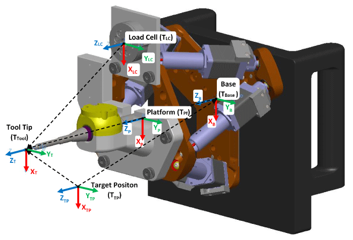
A six degree of freedom (6DOF) Stewart Platform robot was custom-made, based on a class of hexapod parallel robots (Figure 1). It was constructed of six linear stepper motors, each spanning between a base and a platform, on which each motor pivots via ball-socket joints. Its hexapod configuration transforms the linear motor displacements into complete 6DOF motions that include all possible translations and rotations (i.e. poses), within its range of motion. The hexapod configuration was selected for its high power to weight ratio, its structural stiffness through truss triangulation, and its inherently very small range of motion (ROM), which are all important traits for avoiding unsafe failure modes. Additionally, its power to weight ratio allowed for a compact design (204.5mm x 187.8mm x 152.3mm), which meant that it could be suspended on a non-modified intra-operative limb positioning arm (Spider2, Smith & Nephew, London, UK), allowing for it to be easily integrated into existing surgical theatre workflows. The robot was fitted with a Midas Rex bone burring tool (Medtronic, Minneapolis, Minnesota) with a 4mm diameter spherical cutter in order to achieve glenoid preparation by means of a milling process.
A novel motion tracking system was developed to provide real-time pose feedback for closed-loop position control. This new tracking modality utilizes elastic metal strips that tether the robot to the scapula via a patient-specific 3D printed bone mount (Figure 1). The metal strips connect to the robot via a 6DOF load cell; thus, as the robot moves relative to the scapula, the elastic bending and twisting of the strips creates reaction loads, which the closed-loop control software transforms into Cartesian displacement commands. This method will be herein after referred to as Force-Space Navigation, since it navigates the robot by minimizing errors of target loads measured in a force space that is coincident with the Cartesian space. In essence, the Force-Space Navigation modality “feels” its way around within a force-space that is calibrated to the Cartesian coordinate space. The calibration process used in this study is described in the Robotic Procedure section to follow.
Once calibrated, a coordinate transformation allows force-torque measurements to be converted into translations and rotations of target poses (Figure 2). The Force-Space and Cartesian space coordinate frames were co-located to the tool tip, and target positions were transformed to the tool tip through the following equation:
(1)
= Target Position with respect to Tool Coordinate System
= Robot Platform with respect to Tool Coordinate System
= Robot Base with respect to Robot Platform
= Target Position with respect to Robot Base
Similarly, the load cell’s coordinate frame was transformed to the tool tip as follows:(2)
= Measured Load with respect to the Tool Coordinate System
= Load Cell with respect to Tool Coordinate System
= Measured Load with respect to Load Cell
This produced a virtual load cell at the tool tip where the Force-Space Navigation loads from the metal strips were measured, while isolating the real load cell from burring force dynamics that would otherwise have polluted the navigation forces. Burring vibrations were also filtered from the load cell output with a double Butterworth low pass filter with a cutoff frequency of 50 Hz.
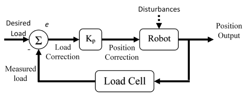
Errors in the force-torque target values were corrected with linear and angular displacements using a closed-loop proportional control scheme (Figure 3). Linear force errors were scaled as 4 mm/N in x, y, z directions, and torque errors were scaled as 5°/N·m about the x, y, z axes. This was done by multiplying the force-torque errors by a 6-term Kp vector of scalars (4, 4, 4, 5, 5, 5) to convert Force-Space (Fx, Fy, Fz, Tx, Ty, Tz) to Cartesian space (X, Y, Z, Rx, Ry, Rz). These Cartesian values are then used as a corrective transform representing a relative step for the robot. For each control point in the desired path, the error minimization loop ended when the error closed to within correction thresholds of ±0.10 N for x and y directions, ±0.07 N for the z direction, and ±0.007 N·m for each rotation. These values were determined through pilot tests with sawbone blocks. The same control loop corrects for unknown movements that can occur. For example, relatively low flexural stiffness of the Spider2 positioning arm and shifting of the specimen as a result of navigation reaction forces can cause unplanned movements.
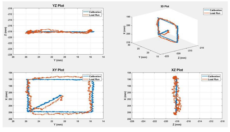
A sample accuracy assessment from the development of the Force-Space navigation method is shown in Figure 4. A simple 10 × 10 × 0mm square path was first recorded (blue) using an optical tracking system (Optotrak Certus, NDI) while running the robot through the target path using its own open-loop motion with the robot’s base rigidly clamped to the bench. The robot was then released from the clamp and allowed to suspend freely on the Spider2 arm. Force-Space navigation was then performed while recording positions (red) with the same optical tracker. The corners of the square were used as control points to measure error and the test was repeated 5 times. The absolute X, Y, Z and Euclidian errors were 0.14 ± 0.19mm, 0.31 ± 0.34mm, 0.19 ± 0.22mm and 0.41 ± 0.46mm, respectively. These errors include compensation for aberrant motions caused by the metal strip reactions forces and relatively low stiffness of the Spider2 arm.
Experimental approach
The robotic system was compared against a fellowship-trained shoulder surgeon who used traditional surgical technique and guides for glenoid reaming. The robot and surgeon prepared the same number of glenoids, which then received cemented all polyethylene glenoid implants. The outcome measures were accuracy of the final implant placement. As the primary objective was to assess accuracy of the robot’s novel position tracking modality, this investigation was conducted in sawbone models to control for specimen variability; thus, all factors that might affect accuracy were equal for the robot and the surgeon.
To test the system’s efficacy in relevant patient pathologies, two different scapula models were used: one with standard glenoid anatomy representing a Walch Type A1 symmetric osteoarthritic patient, and the second with posteroinferior glenoid bone loss representing a Walch type B2 glenoid [18]. Both the surgeon and the robot repeated the task on six specimens of each pathology type. Additionally, in order to assess the system’s applicability to common implant types, both keeled and pegged glenoid implant designs were used.
Pre-operative plan
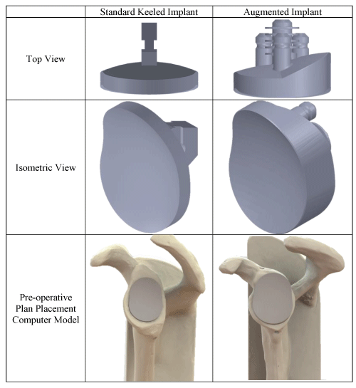
Each scapular Sawbones model was scanned using a clinical Computed Tomography (CT) scanner (0.625mm isotropic voxels, 120 kVp, 200 mA; GE Discovery CT750 HD, Milwaukee, WI, USA). The scapula DICOM was segmented and converted to a Stereolithography (STL) 3D CAD model, which the surgeon used to virtually place an implant 3D CAD model in the desired location on the scapula. The implants utilized were a keeled Aequalis™ Perform™ and a pegged Aequalis™ Perform Plus™ with a 25° wedge (Wright Medical Group, Memphis, Tennessee), for the Walch Type A1 and B2 scapulae, respectively (Figure 5). The 25° posterior wedge of the Perform Plus™ was selected to compensate for the B2 posterior erosion, as is indicated for clinical treatment.
A coordinate frame was defined for the glenoid using anatomical landmarks selected by the surgeon with positive axes directed superiorly, anteriorly, and laterally. A similar implant coordinate frame was also defined and upon final positioning, the implant’s location relative to the glenoid, as well as version and inclination angles, defined the pre-operative plan for both the surgeon and robot. The resulting target values for all specimens are listed in Table 1.
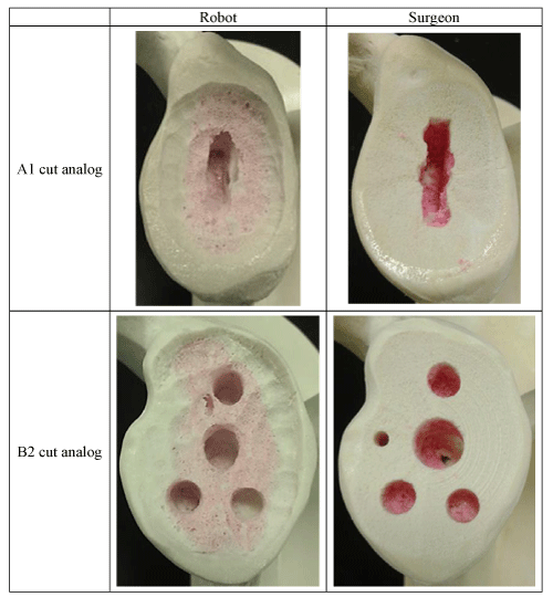
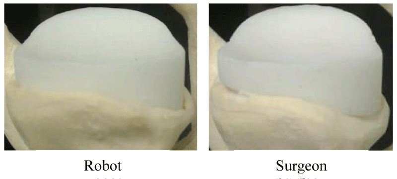
Since the robot utilized a small diameter spherical cutter (4mm burr), this afforded the ability to remove only the bone minimally required to seat the implant. This resulted in preservation of the bone on the periphery of the glenoid, which resulted in inlaying of the glenoid implant. This contrasts with standard surgical reamers, which remove bone uniformly from the entire glenoid face, leaving the implant in an onlayed position. Figure 6 illustrates examples of completed specimens with glenoid bone beds prepared by both robot and surgeon. The robot’s pre-op plan utilized the same burring tool to mill out cancellous bone to accommodate the implant keel or peg fixation features, which is also contrasted with traditional surgical sets that use additional drills and guides to drill holes.
Robotic procedure
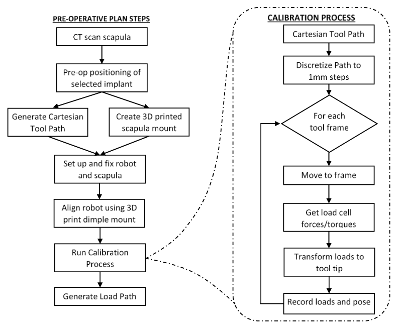
The pre-operative plan workflow, as well as the calibration process for generating a target load path, are described in Figure 7. During the pre-operative plan phase, a CAD model of the 3D printed scapular mount was modified to fit the specimen. The predesigned mount had three bone pedestals that were cannulated for bone screws, and it was designed to engage two pedestals on the coracoid process and one pedestal on the tip of the acromion process. The mount’s orientation was planned to be patient-specific so as to position the burring tool near the glenoid center, with a standard curvature of the navigation strips, thus allowing maximum range of motion for the robot.
With the pre-operative plan set, the implant’s CAD model was subtracted from the scapula 3D model in order to reveal the planned bone removal. This negative space was then converted into a cut path using BobCAD (BobCAD - CAM Inc., Clearwater, Florida, US) software, which generated GCode for a milling machine process with a 4mm spherical burr at 2mm stepover and 1mm depth of cut spacing. The GCode path was then parsed and decimated to define control points at 1 mm spacing. The final list of target control points was defined in xyz Cartesian coordinates relative to the native CT coordinate frame.
Force-Space calibration requires that the pre-operatively planned path be converted into force-torque targets. For this study, the chosen process was to fix the robot’s base relative to a scapular model. The 3D printed scapular mount was attached to the coracoid and acromion processes, and the Metal Strips were connected. Then the robot was commanded to move through the pre-operative path in open-loop position mode, visiting each xyz control point while the load cell recorded the corresponding forces and torques resulting from elastic deformation of the metal strips. No burring occurred during this calibration process. The result was a list of force-space control targets with axial forces measured in N and torques in Nm.
After Force-Space calibration, the experiment was setup to conduct robotic specimen burring. Each test specimen was mounted as shown in Figure 1. The robot’s base was not fixed, but rather suspended from the Spider2 orthopaedic positioning arm in a clinically relevant setup. Additionally, the specimen clamp was mounted on compliant rubber bushings to allow unknown specimen movement as a result of burring forces and reaction forces from the metal strips. This was done in order to model the clinical scenario in which the scapula moves as surgical forces are applied.
The flexible metal strips were connected to the specimen via the patient-specific 3D printed mount, which also achieved registration of the pre-operative plan. This registration was confirmed with another 3D printed patient-specific mount that snapped onto the glenoid face and had 6 fiducial dimples designed to engage with the burr. The load cell was fitted with a rigid joystick threaded into the load cell’s measurement-side, which was used to manually navigate the burr into each dimple by applying forces to the joystick. Manual navigation was achieved by setting force-torque targets to zero, and the same closed-loop force controller reacted to the user’s manual guidance. Thus, the user overcame the reaction forces of the flexible strips, causing the robot to move, and similarly, the robot would stop when the user released the joystick. Threshold load values were added for each force direction (X = ±7 N, Y = ±7 N, Z = ±10 N) to prevent the strips from returning the robot to the origin. As well, rotations were ignored for easier usability. In this way, the robot acted as the digitizing stylus. Any disagreement between the measured locations of the dimples compared to the calibration phase was measured.
An optical tracking system (Optotrak Certus, NDI, Waterloo, ON) was used to quantify the unplanned relative movements arising from the unknown stiffness of the entire system, including aberrant movements due to the flexible specimen mount and low stiffness of the specimen itself, as well as unplanned movements due to the relatively low stiffness of the Spider2 arm. The resulting path errors were also measured using the optical tracker, defined as the achieved position of each control point relative to the planned target position. The optical tracker was an independent third-party observer and was not integrated with the robotic system in any way.
Traditional surgical procedure
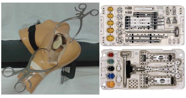
For the traditional surgical technique, the scapula models were attached to a table at an angle consistent with a beach chair patient position (Figure 8). As well, a silicon shoulder (model SKU #1509-24-4 from Sawbones) was added to simulate the surgical exposure of a standard anterior approach. Surgical tool sets corresponding to the implants were used according to the manufacturer’s instructions [19,20] (Figure 8). Unlike the robot, the standard surgical sets use additional drills and guides to drill holes for the implant fixation features.
Analysis
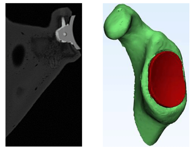
Immediately following each glenoid bone bed preparation, whether by robot or by traditional procedure, a surgeon cemented the implant using Polymethylmethacrylate (PMMA) bone cement. Then all the cemented scapulae were CT scanned (Figure 9). From the pre- and post-operative CT scans, the scapulae and implants were segmented and converted to 3D Stereolithography (STL) CAD files (Figure 9). The post-op scapula model was aligned to its corresponding pre-op scan model using a global registration function (3-Matic, Materialise, Leuven, Belgium), in order to obtain a common measurement frame. The resulting spatial coordinate transformation was then applied to the post-op implant model in order to measure the implant’s pose relative to the scapula, and in comparison, to the pre-operative plan. In order to define the implant’s pose in clinically relevant terms, an anatomical coordinate frame was defined for the glenoid using anatomical landmarks selected by the surgeon, with positive axes directed superiorly, anteriorly and laterally. The implant had a similar coordinate frame that allowed measurement of xyz location coordinates and angles of version, inclination and rotation on the glenoid face.
To assess differences between the two techniques, a one-way repeated-measures MANOVA test was performed comparing the three orthogonal directions, net position, three orientation angles, and net angle of the robot and surgeon implant position error for both the Walch Type A1 and B2 scapula models. Statistical significance was set at p < 0.05, and a Bonferroni correction was applied.
Results
Force-Space navigation accuracy
The robot’s position error was compared to the pre-op planned pathway using an Optotrak Certus optical tracking system (Table 2). The robot’s path error for the standard keel and augmented implants was 0.6 ± 1.0mm and 0.7 ± 1.2mm, respectively. The system’s ability to compensate for unplanned compliance of the Spider2 positioning arm and the flexibility of the specimen and its mount were also measured (Table 3). Over a working volume of XYZ = 52×52×25mm, the complete system experienced a maximum 4.6 mm movement in the anterior-posterior direction as the robot tool moved 26mm in the anterior direction. The Force-Space Navigation controller compensated for this unknown compliance with the path errors stated above.
Walch type A1 shoulder modeling symmetrical erosion
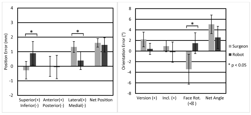
The net implant positioning error for the robot and surgeon were 1.5 ± 0.5mm and 1.6 ± 0.3mm, respectively. Direction-specific errors are shown in Figure 10. Significant differences in position error between the robot and surgeon were found in the superior-inferior and lateral-medial directions (p = 0.03), with the robot’s glenoid preparation resulting in an error of 0.89 ± 0.81mm superior, and the surgeon 0.3 ± 0.6mm inferior. Both the robot and surgeon produced laterally biased errors of 0.4 ± 0.6mm and 1.3 ± 0.4mm, respectively (p = 0.002).
Implant orientation errors were measured in terms of version, inclination, and face rotation (counter-clockwise positive). The net rotation error for the robot and surgeon were 2.6 ± 2.3° and 5.0 ± 1.9°, respectively (Figure 10). A significant difference was seen in face rotation, with the robot producing 1.5 ± 2.2° counter-clockwise error, and the surgeon 3.4 ± 3.1° clockwise error (p = 0.028).
Walch type B2 shoulder modeling posterior erosion
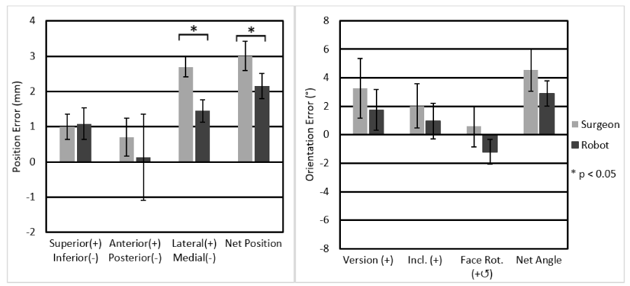
In the Walch type B2 cases, the robot was able to preserve a peripheral ridge of bone surrounding the implant, even around the augmented posterior portion (Figure 11). The B2 shoulders were analyzed in the same manner as the A1 shoulders. Significant differences were found in lateral-medial and in the net position. The net position error for the robot and the surgeon were 2.2 ± 0.4mm and 3.0 ± 0.4mm, respectively (p=0.002), and all position measurements are plotted in Figure 12 In the lateral-medial direction, the robot and surgeon errors were 1.4 ± 0.3mm and 2.7±0.3mm lateral, respectively (p=0.001). The net orientation errors for the robot and surgeon were 2.9 ± 0.9° and 4.5 ± 1.5°, respectively (Figure 12). No significant differences were found for orientation errors.
Intra-observer effects from morphology and implant design
A second MANOVA was performed with implant type as a factor, in order to detect whether the robot or surgeon performance were affected by the symmetrical Walch type A1 erosion model treated with the standard keeled implant, versus the Walch type B2 treated with the pegged augmented implant. The robot showed a significant difference only in the medial-lateral direction with 1.1 ± 0.8mm more error lateral error with the augmented implant (p=0.026). In contrast, the surgeon produced statistically significant errors in five metrics. The surgeon placed the standard implant with 4.0 ± 3.0° more clockwise face rotation compared to the augmented (p=0.022). The four remaining significant surgeon placement errors were all in positional placement, with the augmented implant experiencing higher positional errors than the standard implant. Compared to the standard implant, the surgeon placed the augmented implant more superior by 1.3 ± 0.8mm (p=0.015), more anterior by 0.7 ± 0.5mm (p=0.024), more lateral by 1.4 ± 0.4mm (p=0.001) and with a significantly greater net position error of 1.4 ± 0.5mm (p=0.001).
Discussion
Total Shoulder Arthroplasty (TSA) is an effective treatment for improving quality of life for patients, however suboptimal preparation of the bone bed is still believed to be the primary cause of premature glenoid implant failure [1-9]. While arthroplasty robotics can improve accuracy and reliability, their adoption remains very low due to the challenge of integrating them into the surgical workflow. This study introduces a small robotic platform that is designed to be handled as a tool, and a novel navigation modality that is less obtrusive. The purpose of this study was to test a new Force-Space Navigation system and assess the overall efficacy of this robotic procedure for TSA.
This study demonstrated the viability of the system for glenoid preparation against a fellowship-trained surgeon, in the context of preparing the glenoid bone bed for both standard glenoid components and augmented glenoids used in the treatment of Walch type B2 shoulders. The robot was able to match or outperform the surgeon in most metrics. The surgeon outperformed the robot in only one metric, superior-inferior position; however, the robot’s average error was still less than 1 mm, which may not have clinical significance.
The accuracy of the traditional surgical technique was affected by the morphology and implant type, with the augmented implant experiencing statistically greater errors in all positional metrics, and with the standard implant experiencing greater face rotation error. While not all error metrics were significantly different between the surgeon and robot, it is worth noting some maximums. The surgeon consistently demonstrated a positive version error, with some specimens greater than +5.0° version error, while the robot produced a max version error of 3.6°. The surgeon produced high face rotation errors with the standard glenoid (max. -7.4°) but not with the augmented implant, which is readily explained by the spherical versus keyed backside geometries of these implants. This was reversed for position error, for which the surgeon produced a max. 3.5mm net position error for the augmented implant, and less than 2 mm net error for the standard implant.
This compact robot was affixed to a commercially available intra-operative limb positioning arm (Spider2), which allows it to be compatible with typical operating room equipment. The surgeon attaches the robot to the limb positioner and then manually brings the robot within reach of the glenoid, which is in contrast to existing robots that are floor mounted and must have a wide range of motion in order to achieve the initial approach. Another contrasting feature is that the intra-operative registration of the pre-operative plan is provided by the patient-specific 3D printed mount, with confirmation by having the robot visit alignment targets. Most contemporary systems use a hand-held surface digitizer probe, in conjunction with a tracking system, to perform intra-operative registration. Conceivably, this new method may potentially save time in the initial registration step; however, this requires further evaluation to confirm.
The robot was programmed to preserve a periphery of bone surrounding the implant. This surely resulted in less bone removal than the traditional surgical reaming method, although the actual amount was not measured. The advantages of preserving this periphery compared to reaming it away requires further investigation. Gunter, et al. [21] showed, through finite element analysis and mechanical simulation, that an inlay glenoid design had reduced stress on the glenoid backside and cement interface versus an onlay glenoid, a more uniform stress distribution and significantly less polyethylene edge displacement. Gunther, et al. [22] also used a glenoid inlay design to treat seven patients with severe bone deficiency, and reported improved outcomes with better range of motion and reduced pain. Gagliano, et al. [23] performed cadaveric cyclic loading on inlay versus onlay glenoid implants, and showed the inlay glenoids were less susceptible to loosening. However, concerns also exist with the inlay technique. When inlaying the glenoid, careful consideration must be made for the depth of bone removal. A study by Walch, et al. [24], showed surgeons who tried to preserve the subchondral bone had lower clinical and radiolucent loosening compared to those who reamed aggressively. As well, Sowa, et al. [25] demonstrated that glenoid implants cemented into shoulder analogs with the subchondral bone removed had significantly more micromotion versus shoulders with preserved subchondral bone when put through 10,000 cycles. Thus, the preservation of subchondral bone is an important factor in preventing glenoid implant loosening.
This study had some limitations. As a proof of concept, this study utilized synthetic shoulder analogs in order to facilitate performance assessments for this first implementation. As such, there remain many questions about soft tissues and how accuracy might be affected by mounting the navigation system to real anatomy. The burr’s angle of approach was perpendicular to the glenoid, which is not typical in comparison to a more standard anterior approach. In a real anatomy implementation, perhaps an angled neck burr may be required to avoid the proximal humerus. A practical limitation is the calibration method used, which utilizes the robot to perform the planned motion while the load cell records force-torque path. In order to implement this calibration method clinically, one would have to 3D print a partial scapula model of the patient. Thus, a computational calibration method should be explored; one that is integrated into the pre-operative planning phase.
This study employed simple closed-loop proportional control, and it is well known that a proportional only controller without an integral term will always leave a lag error positional offset. The nature of milling is that the burr passes through control points, removing bone wherever it goes; thus, it is not a disadvantage to have a lagging offset. In fact, early tests showed that an integral term caused the burr’s location to momentarily oscillate around control points, thus revisiting locations where it had already removed bone, which reduced efficiency. Therefore, in this first implementation, correction thresholds determined when position error was sufficiently minimized. Overall, the Force-Space controller achieved submillimeter errors while compensating for unknown compliances, mimicking a slightly mobile scapula, as high as 4.6mm.
Conclusion
This introduction to Force-Space Navigation demonstrates that a robot can be navigated with closed-loop force feedback through flexible components that tether it to bone. It further demonstrates that unknown relative movements of the anatomy, or of the robot’s own support, can also be compensated while following the planned path. Additionally, this system can be programmed to prepare any shaped glenoid for any shaped implant design, which can simplify arthroplasty procedures. Overall, the robot matched or outperformed the fellowship trained experienced shoulder arthroplasty surgeon in most measures of final implant placement. Thus, the robot compared well with a specialist; however, the true value of the robot likely lies in the average orthopaedic surgeon who has far less experience, especially with complex cases, such as Walch type B2 glenoids.
The authors would like to thank Wright Medical Group Inc., for allowing the use of their B2 shoulder analog molds and for providing the surgical tooling for the surgeon’s tests.
Funding
This study was funded by The Natural Sciences and Engineering Research Council of Canada (grant number RGPIN/418656-2013).
- Padegimas EM, Maltenfort M, Lazarus MD, Ramsey ML, Williams GR, et al. (2015) Future patient demand for shoulder arthroplasty by younger patients: national projections. Clin Orthop Relat Res 473: 1860-1867. Link: https://bit.ly/3dfGfBv
- Carter MJ, Mikuls TR, Nayak S, Fehringer EV, Michaud K (2012) Impact of Total Shoulder Arthroplasty on Generic and Shoulder-Specific Health-Related Quality-of-Life Measures: A Systematic Literature Review and Meta-Analysis. J Bone Joint Surg Am 94: e127. Link: https://bit.ly/3uUEmQN
- Hasan SS, Leith JM, Campbell B, Kapil R, Smith KL, et al. (2002) Characteristics of unsatisfactory shoulder arthroplasties. J Shoulder Elb Surg 11: 431-441. Link: https://bit.ly/3a7lea2
- Hopkins AR, Hansen UN, Amis AA, Emery R (2004) The effects of glenoid component alignment variations on cement mantle stresses in total shoulder arthroplasty. J Shoulder Elb Surg 13: 668-675. Link: https://bit.ly/3wR0cWV
- Bonnevialle N, Melis B, Neyton L, Favard L, Molé D, et al. (2013) Aseptic glenoid loosening or failure in total shoulder arthroplasty: Revision with glenoid reimplantation. J Shoulder Elb Surg 22: 745-751. Link: https://bit.ly/2Rtbctj
- Wiater JM, Fabing MH (2009) Shoulder arthroplasty: prosthetic options and indications. J Am Acad Orthop Surg 17: 415-425. Link: https://bit.ly/2PTGBFa
- Flurin PH, Janout M, Roche CP, Wright TW, Zuckerman J (2013) Revision of the loose glenoid component in anatomic total shoulder arthroplasty. Bull NYU Hosp Jt Dis 71: 68-76. Link: https://bit.ly/3tgZP63
- Bohsali KI, Bois AJ, Wirth MA (2017) Complications of Shoulder Arthroplasty. J Bone Joint Surg Am 99: 256-269. Link: https://bit.ly/3a7lwxE
- Matsen FA, Clinton J, Lynch J, Bertelsen A, Richardson ML (2008) Glenoid Component Failure in Total Shoulder Arthroplasty. J Bone Joint Surg Am 90: 885-896. Link: https://bit.ly/3wW1ShO
- Antuna SA, Sperling JW, Cofield RH, Rowland CM (2001) Glenoid revision surgery after total shoulder arthroplasty. J Shoulder Elbow Surg 10: 217-224. Link: https://bit.ly/3wTHez2
- Moreschini F, Colasanti GB, Cataldi C, Mannelli L, Mondanelli N, et al. (2020) Pre-Operative CT-Based Planning Integrated With Intra-Operative Navigation in Reverse Shoulder Arthroplasty: Data Acquisition and Analysis Protocol, and Preliminary Results of Navigated Versus Conventional Surgery. Dose-Response 18: 1-11. Link: https://bit.ly/3gamm0u
- Karelse A, Leuridan S, Van Tongel A, Piepers IM, Debeer P, et al. (2014) A glenoid reaming study: How accurate are current reaming techniques? J Shoulder Elb Surg 23: 1120-1127. Link: https://bit.ly/2Q3XCfN
- Jacquot A, Gauci MO, Chaoui J, Baba M, Deransart P, et al. (2018) Proper benefit of a three dimensional pre-operative planning software for glenoid component positioning in total shoulder arthroplasty. Int Orthop 42: 2897-2906. Link: https://bit.ly/3uPc1Lv
- Stokes IAF (1999) Research Into Spinal Deformities 2. IOS Press. (Studies in health technology and informatics). Link: https://bit.ly/3ddRvhy
- Lang JE, Mannava S, Floyd AJ, Goddard MS, Smith BP, et al. (2011) Robotic systems in orthopaedic surgery. J Bone Joint 93: 1296-1299. Link: https://bit.ly/3uRWH0v
- Jacofsky DJ, Allen M (2016) Robotics in Arthroplasty: A Comprehensive Review. J Arthroplasty 31: 2353-2363. Link: https://bit.ly/3e13D4L
- Birkfellner W, Watzinger F, Wanschitz F, Ewers R, Bergmann H (1998) Calibration of tracking systems in a surgical environment. IEEE Trans Med Imaging 17: 737-742. Link: https://bit.ly/32euPaW
- Walch G, Badet R, Boulahia A, Khoury A (1999) Morphologic study of the Glenoid in primary glenohumeral osteoarthritis. J Arthroplasty 14: 756-760. Link: https://bit.ly/3gan7GS
- Wright Medical Group (2017) TORNIER AEQUALISTM PERFORM Anatomic Glenoid System Surigcal Technique [Internet]. Memphis, TN. Link: https://bit.ly/2RCnC2p
- Wright Medical Group (2017) TORNIER AEQUALIS PERFORM + CORTILOCTM Augmented Glenoid SURGICAL TECHNIQUE [Internet]. Memphis, TN. Link: https://bit.ly/3wR0Dk1
- Gunther SB, Lynch TL, O’Farrell D, Calyore C, Rodenhouse A (2012) Finite element analysis and physiologic testing of a novel, inset glenoid fixation technique. J Shoulder Elbow Surg 21: 795-803. Link: https://bit.ly/3wVC3hW
- Gunther SB, Lynch TL (2012) Total shoulder replacement surgery with custom glenoid implants for severe bone deficiency. J Shoulder Elb Surg 21: 675-684. Link: https://bit.ly/3e2wKos
- Gagliano JR, Helms SM, Colbath GP, Przestrzelski BT, Hawkins RJ, et al. (2017) A comparison of onlay versus inlay glenoid component loosening in total shoulder arthroplasty. J Shoulder Elbow Surg 26: 1113–1120. Link: https://bit.ly/3wTawxA
- Walch G, Young AA, Melis B, Gazielly D, Loew M, et al. (2011) Results of a convex-back cemented keeled glenoid component in primary osteoarthritis: Multicenter study with a follow-up greater than 5 years. J Shoulder Elbow Surg 20: 385-394. Link: https://bit.ly/3wShUcE
- Sowa B, Bochenek M, Braun S, Kretzer JP, Zeifang F, et al. (2018) The subchondral bone layer and glenoid implant design are relevant for primary stability in glenoid arthroplasty. Arch Orthop Trauma Surg 138: 1487-1494. Link: https://bit.ly/3mI1M94

Article Alerts
Subscribe to our articles alerts and stay tuned.
 This work is licensed under a Creative Commons Attribution 4.0 International License.

 Save to Mendeley
