Annals of Robotics and Automation
Pir sensor based security system
Sanikommu Umamaheswari*
Cite this as
Umamaheswari S (2020) Pir sensor based security system. Ann Robot Automation 4(1): 022-024. DOI: 10.17352/ara.000006In this paper passive Infrared sensor “PIR” based security system is introduced. With this sensor we can save power, and effective management at low cost and requires small memory space. The PIR sensor is responsible for detecting the change in infrared radiation levels when an intruder or human is passed through the system or space where it is arranged. Depending on the change in radiation levels the change in voltages occurs and then with this voltage the signal is amplified and hence the sound will be produced. Thus it is helpful in various applications and areas . This type of system has many advantages compared to the existing system.
Introduction
In general, a normal electronic security system comprises of a transmitter and a receiver. Here the transmitter is used to send or transmit an IR laser and this is received by the receiver. When an intruder walks or pass through the device the IR beam is cut and hence the alarm will be activated. But this type of system has disadvantages like limited range of signal and poor line of sight. These disadvantages can be eliminated using PIR sensor. PIR sensor based security system is a wireless security system in which pyro electric infrared motion sensors are placed in four sides I. E front, back, left and right of the area to be covered. By this it can detect motion from any side and turns on the audio visual alarm. It also displays the side where the motion (intruder) is detected. Here all sensors send signals to the central controller circuit wirelessly.
Generally in security systems, that are used in homes, shops , offices etc infrared or laser transmitters and receivers are used for attaining efficiency and reliability. But these methods require a lots of financial investment and huge infrastructure. A simple cost effective solution for security systems is introduced in this project. Where we will learn about PIR based security alarm system in which a PIR sensor is used in the place of transmitter or receiver. This sensor is helpful in saving power and also it’s implementation is cost effective i.e. low cost.
PIR sensor is the short form of passive Infrared sensor. The main ideology is to provide security. This is based on PIR sensor with an IC that produces siren or buzzer sound. The PIR sensor detects the IR radiation which is emitted from the humans and then it produces a digital output. Mostly it is used in motion detectors, security alarms, and automatic lighting applications. In general they detect movement i.e. changes the amount of infrared radiation. In turn this digital output is given to the Arduino Uno. after getting digital signal from the PIR sensor, the Arduino UNO then triggers the UM3561 siren. Thus it produces the sound when only human is detected. The UM3561 is a ROM IC. It is used to generate ambulance siren, machine gun sound, fire engine siren, police sounds etc.
Circuit components
The circuit components required are as follows:
PIR SENSOR
Arduino UNO
UM3561 SIREN IC
NPN Transistor- 2N2222
Resistors 10K ohm and 220K ohm
Speaker 8inch
Breadboard
Connecting wires
PIR sensor
The PIR sensor is mainly used to detect motion by measuring any change in InfraRed levels emitted by objects. Pyroelectric devices have elements which are made of a crystalline material, means they generate an electric current when they are exposed to InfraRed radiation. Changes in the amount of Infrared falling on such devices then it changes the voltages that are generated. Sensor output usually goes high when it detects motion or movement. Sensor output is then given to RF encoder chip.
Radio Frequency (RF) encoder
Usually, the HT12E encoder chip is used to encode the PIR sensor output into a serial bit streams. Then these are given to RF TX module.
Radio Frequency (RF) transmitter
ASK transmitter here modulates the incoming digital signals from the RF encoder using a 434MHz carrier and transmits it through its respective antenna.
Receiver Unit
This is considered as the central controlling section that receives the signals from any of the four PIR sensors which are located at the transmitter side. It gives audio and visual alarms, and displays the exact side where the motion is detected on LCD1.
Radio Frequency (RF) DecoderHere RF decoder in general HT12D RF decoder chip helps in decoding the bit streams. It also generates parallel 4-bit digital output, which it turn given to the MCU.
Microcontroller (MCU)
The functions of the AT89S52 MCU is mainly divided into 3 types.
Detects side where motion is detected from RF decoder digital output.
Displays the various messages including side of detected motion on LCD1
Turns on speaker and make the LED glows for audio-visual alarm when motion is detected.
The 16 X2 LCD panel is helpful in displaying messages given by the MCU.
Multivibrators
We require two multivibrators. Multivibrators are generally used to convert short sharp pulses into much wider ones for timing applications. Here, one is used for blinking the LED at low or minimum frequency precisely (1Hz -2Hz) and the other one to generate the audio frequency signal (1 K Hz) through the speaker for siren or buzzer.
Construction
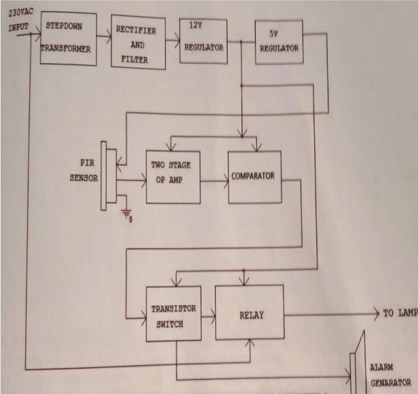
As shown in above figure a 230 V supply is given to step down transformer to convert high voltage or low power into low voltage and high-power Figure 1.
Then it is given to Rectifier and filter section to remove unwanted frequencies or noisy voltages. Then the voltage is regulated in the regulator section. Now the signal is given to operational amplifier and comparator to compare the IR signals. Finally, the signal fed to alarm generator.
Working
As we know that in this proposed system we are using PIR sensors in the place of LASER or INFRARED transmitters and receivers. The sensor is basically a pyro electric device. When the device is in contact with infrared radiation, it generates an electric charge some power like that.
The more in change in the amount of infrared exposed to device, the more the voltage generated, which is measured by an on- board amplifier. The infrared is nothing but light radiating from all objects in their respective surroundings. We don’t need a transmitter or receiver because the device is not able to emit, it only accepts the energy released from things or objects in radiation forms.
Thus the temperature will be different from a moving human and a wall present there which is constant. Thus the word passive in Passive Infrared Sensor explains clearly that it does not emit a radiation rather than it accepts the incoming infrared radiation.
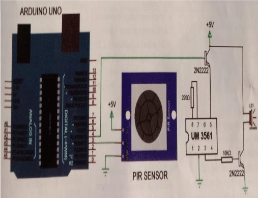
The connections are made according to the circuit diagram shown and switch on the power supply.
The PIR sensor gets power and it detects the IR rays emitted from any intruder who is passing over there.
Usually PIR sensor can vary upto works in a limit of 5 meters. We can adjust the sensor we having to vary the distance.
If any human or intruder is detected, means the PIR sensor outputs a logic of HIGH value i.e. voltage of nearly 3.5 V to 5 V in the Arduino UNO’s PIN 3.
As soon as the Arduino detects logic HIGH on Pin 3, it makes a PIN 4 too HIGH state for a duration of nearly 10 seconds. During this time, the SIREN IC UM3561 it also gets activated as its Pin 5 provided with +5V.
The Siren generator comprises of oscillator internally, to produce the sound in a certain frequency and using 220K ohm resistor externally.
Then it is passed to the control circuit, which depends on tone selection pins.
These tone selection pins decide one tone from different tones produced by the IC.
Thus, oscillation along with selected tone are sent to the address counter. The address counter then sends the data to the ROM, then sends the tone on the output pin 3.
The output is given to the NPN transistor to amplify the siren.
The base of the transistor gets voltage from output pin of the siren generator.
Transistor starts conducting when it gets the cut off voltage at the base and the speaker is negative pin and is connected to ground.
Thus sound produced can be heard from the speaker when human is detected.
The sound can be of various types like ambulance, police, alarm etc.
Code
int pir =4;
int siren =5;
void set()
{
pinMode(pir,INPUT);
pinMode(siren,OUTPUT);
digitalWrite(siren,LOW);
delay(9000);
}
void loop()
if(digitalRead(pir))
{
digitalWrite(siren,HIGH);
delay(11000);
digitalWrite(siren,LOW);
while(digitalRead(pir));
}
Applications
• This system can be used in museums to protect the valuable things.
• Used in automatic door bell system to ring the bell when a human is detected.
• Helpful in defence system to detect the humans in warfield.
• Also used in toys that automatically produce sound.
• To protect the lockers in banks from robbery.

Article Alerts
Subscribe to our articles alerts and stay tuned.
 This work is licensed under a Creative Commons Attribution 4.0 International License.


 Save to Mendeley
