Annals of Mathematics and Physics
Experimental and theoretical studies of the influence of the bench elements on the transient operation of the turbine
AF Salnikov, SV Bochkarev and IA Zubko*
Cite this as
Salnikov AF, Bochkarev SV, Zubko I (2023) Experimental and theoretical studies of the influence of the bench elements on the transient operation of the turbine. Ann Math Phys 6(1): 029-035. DOI: 10.17352/amp.000073Copyright Licence
© 2023 Salnikov AF, et al. This is an open-access article distributed under the terms of the Creative Commons Attribution License, which permits unrestricted use, distribution, and reproduction in any medium, provided the original author and source are credited.The energy parameters obtained during the tests of turbines of power units on the stand differ from those in the product. The research data, which results are presented in the materials of the paper, are aimed at analyzing the discrepancies between the parametric indicators of power units and bench tests of the turbines. The novelty of the obtained results reveals the direct and inverse relationship of changes in the amplitude-frequency characteristics of the elements of the stand (depending on the realized turbine power) with the obtained results of measuring the turbine power on the stand. We developed and described an algorithm for constructing dynamic analysis during the formation of the wave field of the test bench for turbines both in transient modes and in stationary modes corresponding to a constant number of turbine revolutions. It is shown that, by using the algorithm of modal deduction and conditions of dynamic excitation of vibrations from the tested turbine with elements of studying its power, it is possible to construct transients with certain reliability when the number of revolutions of the turbine changes, i.e. its power. The diagnostic model has a novelty since it allows not only to assess of the influence of the elements of the stand on the nature of the transient process when measuring turbine power in transient modes, taking into account the frequency adjustment when changing the revolutions of the turbine and the elements of the stand but also to form requirements for the frequency tuning of the stand. To clarify the transfer function of the "stand–turbine" system, a modal analysis was applied, which made it possible to clarify the structure of the transfer function in the frequency range of the natural (partial) frequencies of the elements of the stand when the restructuring of the wave field during the transient operation of the turbine, but also when the turbine reaches the specified power.
Introduction
When designing power units with turbine engines and upgrading them, it is important to ensure high vibrational reliability. However, when testing the turbine separately from the power unit at the stand, a discrepancy between the test results and the indicators in the power unit, including the level of vibration load, was noted. The basic approach to evaluating the vibration parameters of machines was formulated by Russian and foreign researchers [1-4], which is aimed at evaluating and influencing the elemental base of gas turbines depending on their operating parameters. The developed algorithms make it possible to sufficiently qualitatively investigate these interactions in the structure of changes in the oscillation (rotation) of the rotor part and to construct certain dependencies connecting the dynamic manifestation from the point of view of the formation and maintenance of self-oscillatory processes during the operation of these devices.
In the experimental-theoretical plan of measuring the level of vibrations for research, there is a significant field in the choice of measurement tools. In works [5,6] it is proposed to use fiber-optic sensors for vibroacoustic monitoring. In [7], the relationship between the bearing vibration and the number of defects in bearing units for transmission systems is determined. In [8], the influence of the equipment wear on vibration levels is shown. Therefore, it is important to develop and implement methods aimed at evaluating the dynamic reliability of products and eliminating vibration at the stage of testing them.
A fairly large number of works deal with methods and conditions of conducting research when during turbine tests [9,10]. However, there are few studies on the influence of the elemental base of the stand on the technical device being tested, as applied to the operation of turbines. In this work, an attempt was made to connect the influence of the elements of the turbine test stand with the results of studying the vibrational field of the turbine including the stand. The conditions of the wave interactions of the stand elements on the dynamic behavior of the tested product are analyzed both in stationary modes of its tests and in transient ones. A dynamic model has been developed and an algorithm for calculating the natural frequencies of the bench elements has been developed, which has been verified based on the results of vibration measurements on an existing bench, both during modal studies and during dynamic tests using the IDS software package.
General remarks on the operation of the turbine on the stand
So, during the experimental tests of turbine blocks of the power units up to 1 MW on the bench, significant dynamic loads associated with vibrations of both the bench elements and the turbine were revealed, which resulted in test failures. It was revealed that their manifestation increased significantly during transient modes associated with a change in the turbine speed (a change of power). In addition, in the process of a steady state at certain speeds, a non-linear in-time self-oscillatory state of the wave field of the stand with the turbine is noted, which leads to non-calculated readings of its power. As an example, Figure 1 shows a graph of changes in the level of vibration accelerations for the turbine of a turbine unit, obtained on the support of its fastening through a spacer to the bench frame.
A similar image of the change in the vibration load was recorded at all points of measurement of the bench vibration during turbine testing, which led to failures in the operation of the bench equipment.
Assuming that the natural (modal) frequencies of the test bench elements depend on the load associated with a change in the rotational speed of the tested turbine (produced power), it is possible to link the change in power on the turbine with the mode of dynamic restructuring of the modal amplitude-frequency characteristics of the test bench elements. The restructuring of the modal frequencies of the bench elements changes the partial frequencies of the bench and vice versa. In this case, the change in the number of revolutions in time leads to a change not only in the frequency of the dynamic load acting in the elements of the stand but also in a change in the amplitude of the alternating modal frequency in a certain dependence on the turbine speed. This assumption does not contradict the physics of the change in the natural (partial) frequencies of the stand when the load changes (an example of tuning stringed instruments). In this case, the interaction of the element base of the stand under near or resonant interactions of elements during the formation of partial frequencies of the stand is the most characteristic feature of the manifestation of the dynamic nature of the stand and the turbine. The restructuring of the frequency characteristics and the formation of the carrier partial frequency of the bench as a whole occurs not only in the transient mode of changing the turbine speeds but at their fixed value. The wave field of partial frequencies of the bench at each moment tends to form a self-oscillating mode when the vibrational energy of each element of the bench changes, that is, it adjusts to the change in the energy of oscillations inside the bench system. Stand elements interact with each other, being an external dynamic load for each other. This interaction is reflected in the partial frequencies of the stand, which affect the interaction of the elements of the stand. Thus, the system aims at a certain balance with restructuring in the amplitude-frequency region in response to a change in the turbine speed. To understand the reasons for such a dynamic behavior of "floating" of the amplitude-frequency characteristics of the bench, both in transient conditions and in steady state, it is necessary to develop a mathematical model of the stand and a calculation algorithm that allow one to construct the transfer function of the element base of the stand and link the conditions for a possible change in the wave field with the results of measuring the parameters of the turbine operation as part of the stand.
Description of the stand for testing turbines
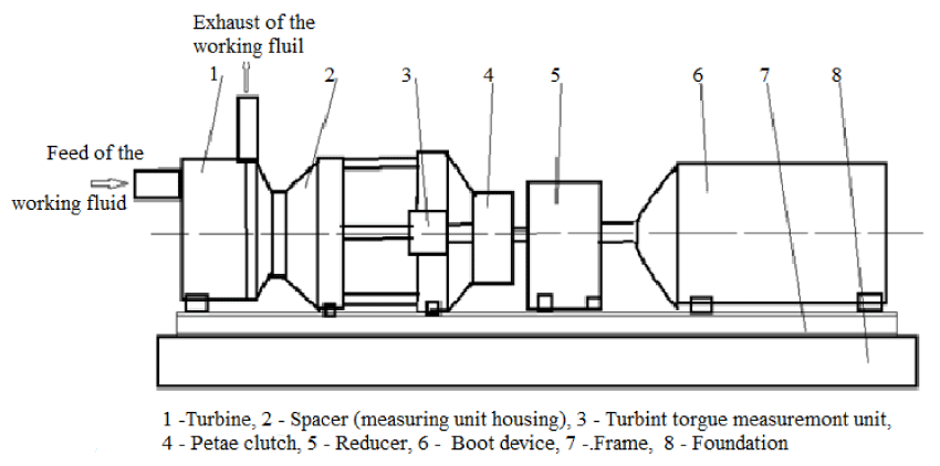
Figure 2 shows a diagram of the bench design. Figure 3 shows a part of the bench with an indication of vibration measurement points during the modal analysis. The tested turbine (Figure 2) is mounted in the transitional unit of the stand, which is called the "spacer" (2). The units for measuring the speed and torque (power), (3), are mounted in this spacer. The torque measuring unit through the petal clutch (4) is connected through the gearbox (5) with the load unit (6). All these devices are mounted on the frame of the stand, which is part of the foundation.
When testing a turbine, a working fluid (air at a temperature of 2930 K) is supplied through its inlet pipe at a pressure of 2.5 MPa to 3.5 MPa. The mass flow rate varies from 5 kg/s to 15 kg/s. These parameters of the working fluid at the entrance to the working area of the tested turbine make it possible to obtain the required power during testing.
The control system for the supply of the working fluid allows you to form certain flow characteristics through the turbine and explore its energy and vibration parameters.
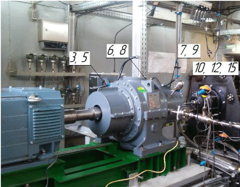
Figure 3 is a part of the stand from the side of the loading device, where the numbers mark some points of measurement of the vibration level on the element base of the stand. The total number of vibration measurement points during the research was more than 40. The numbering of the points did not change during the research of various turbine units. So points 3,5 are points for measuring vibrations in three directions at each point on the housing in the area of bearings of the low-speed shaft of the gearbox. Points 6 and 8 are in the area of bearings of the high-speed shaft. Measuring point 7 is in the area of installation of bearings for measuring torque. Point 9 shows the spacer fixing to the frame of the stand. Points 10, and 12 are in the area of fastening the measuring units. Point 15 is the area of the turbine outlet bearing.
The remaining vibration measurement points were located in the attachment points of the turbine and bench elements to the mounting frame.
This number of points when measuring the vibration level in three directions made it possible to build a dynamic picture of the standing behavior and evaluate the influence of each of the elements on the readings of the torque measurement system both in transient modes and in stationary mode (at a constant turbine speed).
Mathematical model of the stand
A mathematical model and an automated computational algorithm for studying the dynamic behavior of an elemental turbine as part of the elemental base of the bench are built taking into account the wave interactions of its structural elements and assemblies over time, taking into account the change in the turbine speed and its power in the bench. Based on the analysis of real designs of the element base of the stand, a range of initial and boundary conditions was chosen for the mathematical modeling of the dynamic change in the turbine power during its operation taking into account the interaction with the element base of the stand.
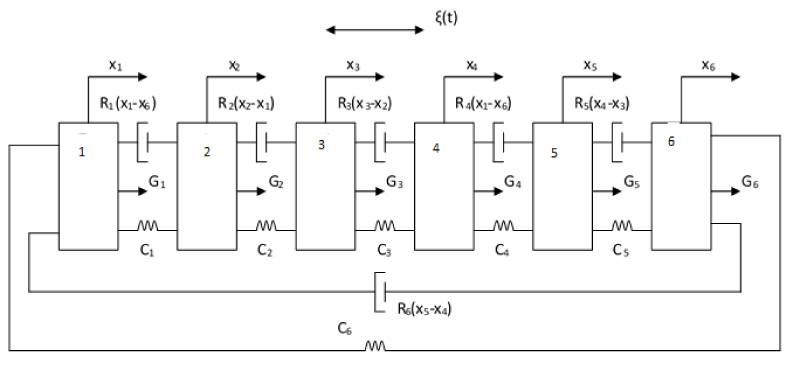
Figure 4 shows the calculation scheme of the stand model, in the form of discrete masses with elastic-dissipative bonds [11-13].
The algorithm of the mathematical model makes it possible to investigate the conditions for the occurrence of increased dynamic loads acting on the measuring base of the bench. In this case, the influence of frequency interactions is taken into account when changing the number of revolutions of the turbine and measuring its power. The change in the modal frequencies of the elements and the partial frequencies of the stand from the load is modeled when the turbine speed changes.
The algorithm for determining the natural frequencies of the bench elements is based on a mathematical model as a system of discrete masses with elastic-dissipative constraints.
A generalization of the calculation scheme is the introduction of elastic-dissipative bonds between non-neighboring chain masses [9,10].
To determine the natural frequencies of oscillations of the elements of a stand with a turbine, an algorithm was developed based on oscillations of a multi-mass model with n degrees of freedom taking into account torsional vibrations. Natural oscillations of the i-th element of a system of n elements are described by a system of differential equations.
Where mi is the mass of the i-th element of the system; хi is the amplitude of movement of the center of mass of the element; ω is the circular frequency of vibrations of the center of mass of the element; Ci is the rigidity of the connection of the i-th element of the system.
In the matrix form, the displacement amplitude by the Maskwell-Mohr method was found as follows
[mi]{ȕ} +[C] {u} = 0 (2)
where {x} is a column vector of displacements; {𝑢̈} is the column vector of accelerations, [m] and [C] are the mass and stiffness matrices, respectively.
The differential equation characterizing the free torsional vibrations of a multi-mass model can be represented by the matrix form
[I]{ε} +[Cφ]{φ} = 0 (3)
where {ε} is the column vector of angular accelerations; {φ} is the shaft twist angle; [I] and [Cφ], respectively, are the matrices of the moment of inertia and the angular stiffness of the model elements.
The frequency of natural vibrations of each element of the system in general terms can be represented by the expression
where f = с-1 is the unit compliance corresponding to the quasi-elastic coefficient с.
For a system of discrete masses, the expression for the natural frequency spectrum will be:
ω1 ≤ ω2 ≤ ω3 ≤ ω4 ≤ ω5 ≤ ω6
The natural frequency equations will be determined by the following matrix
The general solution of the equation of free oscillations with natural frequency ωа and natural form va will look like:
To simplify the solution of this complex system of equations, it is necessary to divide it into six subsystems, i.e. partial systems. To do this, it is necessary to find the partial frequencies of each element of the system. These frequencies will coincide system when: А12 = А21 = 0; С12 = С21 = 0:
Where ωI, ωII, ωIII, ωIV, ωV, and ωVI are partial frequencies of the components of the element base of the stand, respectively. Using this method, an algorithm for finding the natural frequencies of the bench elements was compiled using the analysis of four subsystems in the MathCAD application package.
The results of the frequency analysis of the modal characteristics of the stand were verified by the results of the modal analysis performed on the stand.
Experimental part
In the experimental part, the general task of the research is reduced to two studies:
- Finding natural (modal) frequencies of the element base of the stand.
- Evaluation of their change under the action of a load within the range of the measured power.
In addition, an assessment is made of the change in the partial frequencies of the stand as a whole, as a multi-mass system. The solution to this problem makes it possible to evaluate the priority influence of the natural (modal) frequencies of the wall elements on the partial frequencies of the stand as a whole.
Evaluation of natural torsional vibrations of the rotor elements of the stand was carried out according to a similar algorithm, which made it possible to evaluate the effect of natural torsional vibrations of the measuring spring installed in the spacer on the results of the power evaluation when testing the turbine as part of the stand and to build a relationship between the change in natural frequencies of the spring depending on the number of revolutions (measured power) turbines.
Comparison of the results of the modal analysis of an unloaded bench carried out on its elemental base and fitting to the experimental frequencies of the above algorithm made it possible to refine matrix С of quasi-elastic coefficients at zero loads, which made it possible to predict the change in the matrix of quasi-elastic elements depending on the load implemented on the loading device of the bench directly on the measuring spring used as a turbine power sensor.
As an example, Table 1 shows the results of studying the modal frequencies of the test bench elements for constructing the transfer function from the turbine (point 15) to the fastening of the spacer to the frame (point 9) and to the moment measurement unit in the spacer (point 7, see Figure 3). To construct the transfer function of the test bench elements, the results of studies of model frequencies are used at all points of measurement of the passage of the impulse load.
Modeling according to the developed algorithm for calculating the change in the partial frequencies of the element base of the stand depending on the number of revolutions of the turbine agrees quite well with the results of modal analysis when estimating the transfer function from the turbine to the frame.
Modal analysis results
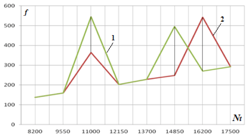
As an example, Figure 5 shows the results of tuning the partial frequencies of the stand at the point of attachment of the spacer to the frame from a change in the number of revolutions of the turbine. The frequency analysis was carried out when processing the time signal, "cut" from its time implementation in accordance with the example of vibration measurement of the sensor at point 9 in Figure 1, the cut zones are indicated by numbers from 1 to 7. This made it possible to determine the frequency and amplitude of the carrier signal in each specific temporal implementation during spectral analysis and to associate these frequencies and amplitudes with the conditions for changing the wave (vibration) field of the stand. Since the vibration measurements were carried out by multichannel equipment, this made it possible to synchronize the processing of vibration signals from all sensors, to obtain not only the frequency reconfiguration of the modal frequencies of the bench element base depending on the turbine speed but also determine the phase shifts in the frequency implementation of the formation of the partial frequency of the bench as a whole.
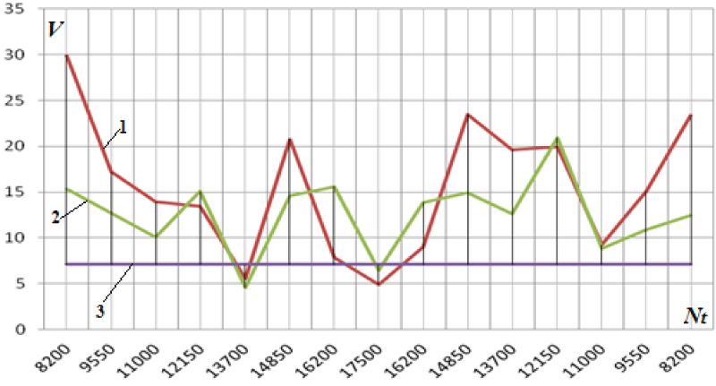
Figure 6 shows the results of the experimental studies of the change in the mean square value (MSV) of the vibration velocity at point 7 depending on the turbine speed from the side of the loading device with a multiplier.
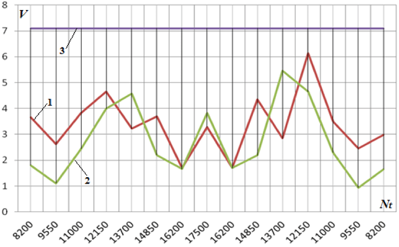
Figure 7 shows the results of measurements of the experimental studies of the change in MSV vibration velocity at point 9 (power measurement unit in the spacer) depending on the turbine speed from the turbine side.
Analysis of the results shown in Figures 5-7 clearly demonstrates the non-linear dependence of the change in the frequency characteristics of the oscillatory processes in the elements of the stand on the number of turbine revolutions (power).
The presented results of studying the dynamic behavior and restructuring of the frequency characteristics of the element base of the stand allow us to explain the non-stationary picture of the manifestation of changes not only in the oscillatory modes but also in the energy of oscillations during transient modes of studying the turbine operation.
Conclusion
The developed mathematical apparatus based on point masses for the stand for testing the performance of turbines of various powers makes it possible to construct the transfer function of the stand depending on the change in the number of turbine revolutions. This algorithm allows you to evaluate the possible level of influence of each of the elements of the stand on the dynamic implementation through the vibration pattern of the process.
Using the results of studying the modal frequencies of bench equipment elements without load made it possible to refine the stiffness function in the algorithm for calculating the partial frequencies of the bench, to obtain transfer functions from the bench element base and the conditions for frequency transformations by the bench element base when the turbine power changes.
The results of the studies made it possible to explain the reasons for the "floating" of the results of measuring the power of the turbine both in transient modes of changing its speed and at steady state speed.
The developed algorithm and the results of the experimental study make it possible to evaluate not only the dynamic state of a particular test bench in different turbine research modes, but also to give recommendations for designing various test benches taking into account the influence of the material base, and therefore predict dynamic loads on the bench element base.
- Goldin AS. Vibration of rotary machines. M: Mashinostroenie. 1999; 344.
- MP. Boyce Gas turbine engineering handbook (4th edition). Butterworth-Heinemann - Elsevier. 2012; 1000. (ISBN: 978-0-12-383842-1)
- Numerical study of the dynamics of vertical-axis turbines / VG Bobkov, AE Bondarev, VTZhukov, KV Manukovsky, ND Novikova, OB Feodoritova// Preprints of IPM im. MV Keldysh. 2019; 119:25s.
- Nasonov DA. Calculation methodology and dynamic analysis of turbo-gear units of the main drive of marine propellers / doctoral dissertation, spec. 02/01/06 Dynamics of the strength of machines, devices and equipment. Moscow. 2014.
- Feng Gao, Yapeng Shen, Luxian Li. The optimal design of piezoelectric actuators for plate vibroacoustic control using genetic algorithms with immune diversity // Smart Mater. Struct. 2000; 9:485-491.
- Takeo Y, ShigeoS. Monitoring of Ball Bearing Operation under Grease Lubrication Using a New Compound Diagnostic System Detecting Vibration and Acoustic Emission // Tribology Transactions. 2009; 52:725-730.
- Francis MC. Reflections on Nonlinear Dynamics of Machines and Structures // Tribology Transactions. 2007; 50:74-81
- Sivakov VP, Vurasko AV, Vikharev SN. Periodicity of equipment diagnostics during vibration control // Repair, restoration, modernization. 2019; 8:24-28.
- Grigoriev VA. Testing and ensuring the reliability of aviation gas turbine engines / FGBOU VPO Samara State Aerospace University. Academician S.P. Queen, Samara. 2011; 112s.
- Skorokhodov AV, Blinov VL, Komarov OV. Testing of gas pumping units and auxiliary equipment / Ural Federal University. First President of Russia BN. Yeltsin, Yekaterinburg. 2020; 132s.
- Pavlov DA, Salnikov AF, Mormul RV. Vibration-based diagnostics and structural analysis of research on nonlinear dynamic processes in maglev-suspension rotor turbomachines // Russian Journal of Nondestructive Testing. 2018; 54: 7; 487-494.
- Salnikov AF. Diagnostics of the technical condition of large-sized parts of gas turbine engines by modal characteristics // Bulletin of the Perm National Research Polytechnic University. Aerospace engineering. 2018; 55: 61-69.
- Kalinin VV. Non-stationary processes and methods for designing units of solid propellant rocket motors / VV Kalinin, VN Kovalev, AM Lipanov. M: Mashinostroenie. 1986.
Article Alerts
Subscribe to our articles alerts and stay tuned.
 This work is licensed under a Creative Commons Attribution 4.0 International License.
 Help ?

PTZ: We're glad you're here. Please click "create a new query" if you are a new visitor to our website and need further information from us.
If you are already a member of our network and need to keep track of any developments regarding a question you have already submitted, click "take me to my Query."



 Save to Mendeley