ISSN: 2689-7636
Annals of Mathematics and Physics
Research Article       Open Access      Peer-Reviewed

Energy and exergy analyses of combustion process in a DI diesel engine fuelled with diesel-biodiesel blends

Shahnaz Habibian1, Rahim Karami2* and Marziyeh Hoseinpour3

1Department of Biosystem Engineering, Shahrekord University, Iran
2Department of Engineering, CQ University, Australia
3Department of Biosystem Engineering, Ferdowsi University of Mashhad, Iran
*Corresponding author: Rahim Karami, Department of Engineering, CQ University, Australia, E-mail: karami.rahim@gmail.com
Received: 01 Febraury, 2021 | Accepted: 13 March, 2021 | Published: 15 March, 2021
Keywords: Biodiesel; Combustion process; Cylinder pressure; Energy; Exergy

Cite this as

Habibian S, Karami R, Hoseinpour M (2021) Energy and exergy analyses of combustion process in a DI diesel engine fuelled with diesel-biodiesel blends.Ann Math Phys 4(1): 001-008. DOI: 10.17352/amp.000018

Exergy analysis is achieved by assessing exergies related to the inlet fuel and air, output power, heat loss, gas exhaust loss and destruction or system irreversibility. The exergy fraction of each component is considered for all mixtures by dividing the individual exergy quantity into the exergy of the fuel. In the present investigation, the combustion process has been simulated in a DI diesel engine (OM314) with biodiesel fuel different Blends (B20, B40, B100) of soybean at full load and 1200 rpm by a thermodynamic model using both thermodynamics first and second laws of thermodynamics. The results showed good agreement with the experimental pressure. The results of the analysis of energy and availability balance show that the first and second laws efficiency for pure biodiesel fuel is more than the other two fuel and total availability. indicated work availability, the heat loss availability, burned fuel availability and irreversibility for 20% biodiesel fuel are more than two other fuels.

Introduction

The availability of adequate amount of conventional fossil fuel for internal combustion engines and the associated effects of global warming and other environmental issues arising due to the combustion of fossil fuels are the two most threaten-ing problems of o- ur present day civilization. Therefore, Ithere is agreat deal of interest and research on both alternative energy resources and their efficient use in thermal engine. Biofuels with the potential of supplying much more energy than the fossil fuel are known as the clean, renewable feedstock. Nowadays biofuels especially biodiesel are considered much more than before [1,2]. Recently, enzymes have been integrated with nanomaterials as immobilization carriers. Nanomaterials can increase biocatalytic efficiency. The development of a nano-immobilized enzyme is one of the key factors for cost-effective biodiesel production. Technology development of nanomaterials, including nanoparticles (magnetic and non-magnetic), carbon nanotubes, and nanofibers, and their application to the nano-immobilization of biocatalysts [3-5]. Thermodynamics laws are one of the best tools for evalution of the prformance of thermal systems such as CI or SI engines. The thermodynamics details of the process of a thermal engine can be clarified by performing an exergy analysis (second law) of the System in addition to an energyanalysis (first law). In fact, an alternative means to select the most convenient biomass, is exergy analysis. This thermodynamic analysis technique estimates the efficiency of the process and dete rmines the energy quality and usefulness [6].

First law analysis or energy analysis is a proper method to predict engine performance and influence of its various operative parameters [7]. On the other hand, it has long been understood that traditional first law analysis, which is needed for modeling the engine processes, often fails to give the engineer the best in sight into the engine’s operation. In order to analyze engine performance, that is to evaluate the inefficiencies associated with the various processes, second law analysis must be applied [8]. For the second law analysis, the key concept is “availability or exergy”. The availability of a matter explains its potential to produce useful work. Unlike energy, exergy is always destroyed when a process is irreversible, for example loss of heat to the environment or due to friction and throttling.

In the past few decade, The exergy analysis of Compression Ignition (CI) engines, also known as the second law or availability analysis, has been studied by many investigators.The first studies of internal combustion engines operation that included exergy balance in the calculations were around 1960, the works of Traupel [9] and Patterson and Van Wylen [10]. Flynn, et al. explained a new observation in internal combustion engine studies. They applied a method based on the second law of thermodynamics for engine analysis [6]. A review paper written by Caton, explains previous studies of engine operation from the second law observation [11]. Exergy analysis on combustion engines performed for many years has been well reviewed and summarized by Carton and Rakopoulos, et al. [8, 11]. Most of these studies were based on exergy analysis of diesel engines fueled with diesel.

There are some studies worked on second law analysis of engines consuming biodiesel-diesel belends. The energy and exergy analysis in a single- cylinder CI engine operated with Diesel fuel and palm biodiesel were carried out by Misra, et al.

They evaluated both the performance and the characteristics of the engine at 85% engine loading and finally concluded that exergetic efficiency is almost equal to energetic efficiency [12]. Caliskan, et al. performed energy and exergy analyses in a turbocharged Diesel engine fueled with pure Diesel as a base fuel and two different biodiesel fuels (soybean oil methyl ester and high-oleic soybean oil methyl ester) [13]. Azoumah et al. Investigated the energy and exergy balance of a DI engine fueled two different biodiesel fuels (cottonseed and palm oils) at different engine loads by using exhaust experimental data [14].

Therefore, the first and second laws of thermodynamics are employed in this study as an environmental assessment tool to account wastes and determine real energy efficiency of Diesel engine fueled with pure Diesel fuel and various blends of soybean oil methyl ester (CME). The biodiesel blends with Diesel from 20%, 40% and to 100% by volume were used to test a commercial agricultural engine. Engine performance data, mean pressure in cylinder and exhaust emissions were recorded. It should be noted that exergy analysis of combustion process in DI diesel engine considered as the main objective of this study. it provides a particular example of a constraint on observable reality imposed by perception.

Material and method

Energy analysis

In the present study, engine operation is analyzed from the first and second law of thermodynamics perspective and the various terms are evaluated. The first law analysis is done by using a Single-Zone model. The combustion chamber is considered as a volume control. For a closed system, first law of thermodynamics energy conservation equation is simply wr tten as [15].

δQ-δW=dU (1)

where δQ partial differential of heat is, δW is Partial differential of work and dU is differential of internal energy. Since δW=PdV, and dU=mc_v dT, the energy equation is therefore.

δQPdV= C v R ( PdV+VdP ) MathType@MTEF@5@5@+=feaaguart1ev2aaatCvAUfeBSjuyZL2yd9gzLbvyNv2CaerbuLwBLnhiov2DGi1BTfMBaeXatLxBI9gBaerbd9wDYLwzYbItLDharqqtubsr4rNCHbGeaGqiVu0Je9sqqrpepC0xbbL8F4rqqrFfpeea0xe9Lq=Jc9vqaqpepm0xbba9pwe9Q8fs0=yqaqpepae9pg0FirpepeKkFr0xfr=xfr=xb9adbaqaaeGaciGaaiaabeqaamaabaabaaGcbaaeaaaaaaaaa8qacaqG0oGaaeyuaiabgkHiTiaabcfacaqGKbGaaeOvaiabg2da9maalaaapaqaa8qacaqGdbWdamaaBaaaleaapeGaaeODaaWdaeqaaaGcbaWdbiaabkfaaaWaaeWaa8aabaWdbiaabcfacaqGKbGaaeOvaiabgUcaRiaabAfacaqGKbGaaeiuaaGaayjkaiaawMcaaaaa@478D@ (2)

By differentiation with respect to crank angle (θ), the following equation is obtained.

dQ dθ =( γ γ1 )P dV dθ +( 1 γ1 )V dP dθ   MathType@MTEF@5@5@+=feaaguart1ev2aaatCvAUfeBSjuyZL2yd9gzLbvyNv2CaerbuLwBLnhiov2DGi1BTfMBaeXatLxBI9gBaerbd9wDYLwzYbItLDharqqtubsr4rNCHbGeaGqiVu0Je9sqqrpepC0xbbL8F4rqqrFfpeea0xe9Lq=Jc9vqaqpepm0xbba9pwe9Q8fs0=yqaqpepae9pg0FirpepeKkFr0xfr=xfr=xb9adbaqaaeGaciGaaiaabeqaamaabaabaaGcbaaeaaaaaaaaa8qadaWcaaWdaeaapeGaaeizaiaabgfaa8aabaWdbiaabsgaiiaacqWF4oqCaaGaeyypa0ZaaeWaa8aabaWdbmaalaaapaqaa8qacqWFZoWza8aabaWdbiab=n7aNjabgkHiTiaaigdaaaaacaGLOaGaayzkaaGaaeiuamaalaaapaqaa8qacaqGKbGaaeOvaaWdaeaapeGaaeizaiab=H7aXbaacqGHRaWkdaqadaWdaeaapeWaaSaaa8aabaWdbiaaigdaa8aabaWdbiab=n7aNjabgkHiTiaaigdaaaaacaGLOaGaayzkaaGaaeOvamaalaaapaqaa8qacaqGKbGaaeiuaaWdaeaapeGaaeizaiab=H7aXbaacaGGGcaaaa@5598@ (3)

where γ is the ratio of specific heats. For each specie i, the thermodynamic quantities specific heat and enthalpy as functions of temperature are given in the form [16]:

C p ~ i R ~ = a i 1 + a i 2 T+ a i 3 T 2 + a i 4 T 3 + a i 5 T 4   MathType@MTEF@5@5@+=feaaguart1ev2aaatCvAUfeBSjuyZL2yd9gzLbvyNv2CaerbuLwBLnhiov2DGi1BTfMBaeXatLxBI9gBaerbd9wDYLwzYbItLDharqqtubsr4rNCHbGeaGqiVu0Je9sqqrpepC0xbbL8F4rqqrFfpeea0xe9Lq=Jc9vqaqpepm0xbba9pwe9Q8fs0=yqaqpepae9pg0FirpepeKkFr0xfr=xfr=xb9adbaqaaeGaciGaaiaabeqaamaabaabaaGcbaaeaaaaaaaaa8qadaWcaaWdaeaadaWfGaqaa8qacaqGdbWdamaaBaaaleaapeGaaeiCaaWdaeqaaaqabeaapeGaaiOFaaaak8aadaWgaaWcbaWdbiaabMgaa8aabeaaaOqaamaaxacabaWdbiaabkfaaSWdaeqabaWdbiaac6haaaaaaOGaeyypa0Jaaeyya8aadaWgaaWcbaWdbiaabMgaa8aabeaakmaaBaaaleaapeGaaGymaaWdaeqaaOWdbiabgUcaRiaabggapaWaaSbaaSqaa8qacaqGPbaapaqabaGcdaWgaaWcbaWdbiaaikdaa8aabeaak8qacaqGubGaey4kaSIaaeyya8aadaWgaaWcbaWdbiaabMgaa8aabeaakmaaBaaaleaapeGaaG4maaWdaeqaaOWdbiaabsfapaWaaWbaaSqabeaapeGaaGOmaaaakiabgUcaRiaabggapaWaaSbaaSqaa8qacaqGPbaapaqabaGcdaWgaaWcbaWdbiaaisdaa8aabeaak8qacaqGubWdamaaCaaaleqabaWdbiaaiodaaaGccqGHRaWkcaqGHbWdamaaBaaaleaapeGaaeyAaaWdaeqaaOWaaSbaaSqaa8qacaaI1aaapaqabaGcpeGaaeiva8aadaahaaWcbeqaa8qacaaI0aaaaOGaaiiOaaaa@5A4C@ (4)

h ~ i R ~ T = a i 1 + a i 2 2 T+ a i 3 3 T 2 + a i 4 4 T 3 + a i 5 5 T 4 + a i 6 T   MathType@MTEF@5@5@+=feaaguart1ev2aaatCvAUfeBSjuyZL2yd9gzLbvyNv2CaerbuLwBLnhiov2DGi1BTfMBaeXatLxBI9gBaerbd9wDYLwzYbItLDharqqtubsr4rNCHbGeaGqiVu0Je9sqqrpepC0xbbL8F4rqqrFfpeea0xe9Lq=Jc9vqaqpepm0xbba9pwe9Q8fs0=yqaqpepae9pg0FirpepeKkFr0xfr=xfr=xb9adbaqaaeGaciGaaiaabeqaamaabaabaaGcbaaeaaaaaaaaa8qadaWcaaWdaeaadaWfGaqaa8qacaqGObaal8aabeqaa8qacaGG+baaaOWdamaaBaaaleaapeGaaeyAaaWdaeqaaaGcbaWaaCbiaeaapeGaaeOuaaWcpaqabeaapeGaaiOFaaaakiaabsfaaaGaeyypa0Jaaeyya8aadaWgaaWcbaWdbiaabMgaa8aabeaakmaaBaaaleaapeGaaGymaaWdaeqaaOWdbiabgUcaRmaalaaapaqaa8qacaqGHbWdamaaBaaaleaapeGaaeyAaaWdaeqaaOWaaSbaaSqaa8qacaaIYaaapaqabaaakeaapeGaaGOmaaaacaqGubGaey4kaSYaaSaaa8aabaWdbiaabggapaWaaSbaaSqaa8qacaqGPbaapaqabaGcdaWgaaWcbaWdbiaaiodaa8aabeaaaOqaa8qacaaIZaaaaiaabsfapaWaaWbaaSqabeaapeGaaGOmaaaakiabgUcaRmaalaaapaqaa8qacaqGHbWdamaaBaaaleaapeGaaeyAaaWdaeqaaOWaaSbaaSqaa8qacaaI0aaapaqabaaakeaapeGaaGinaaaacaqGubWdamaaCaaaleqabaWdbiaaiodaaaGccqGHRaWkdaWcaaWdaeaapeGaaeyya8aadaWgaaWcbaWdbiaabMgaa8aabeaakmaaBaaaleaapeGaaGynaaWdaeqaaaGcbaWdbiaaiwdaaaGaaeiva8aadaahaaWcbeqaa8qacaaI0aaaaOGaey4kaSYaaSaaa8aabaWdbiaabggapaWaaSbaaSqaa8qacaqGPbaapaqabaGcdaWgaaWcbaWdbiaaiAdaa8aabeaaaOqaa8qacaqGubaaaiaacckaaaa@6308@ (5)

In these relations, CP is the specific heat at constant pressure, T is temperature, h is enthalpy, R~ is universal gas constant and ai constant coefficients.

In order to integrate the differential energy equation an equation for the cylin der volume as a function of crank angle is needed as following [17],

dV dθ = V d 2 sinθ[ 1+cosθ ( R 2 sin 2 θ ) 1 2 ] MathType@MTEF@5@5@+=feaaguart1ev2aaatCvAUfeBSjuyZL2yd9gzLbvyNv2CaerbuLwBLnhiov2DGi1BTfMBaeXatLxBI9gBaerbd9wDYLwzYbItLDharqqtubsr4rNCHbGeaGqiVu0Je9sqqrpepC0xbbL8F4rqqrFfpeea0xe9Lq=Jc9vqaqpepm0xbba9pwe9Q8fs0=yqaqpepae9pg0FirpepeKkFr0xfr=xfr=xb9adbaqaaeGaciGaaiaabeqaamaabaabaaGcbaaeaaaaaaaaa8qadaWcaaWdaeaapeGaaeizaiaabAfaa8aabaWdbiaabsgaiiaacqWF4oqCaaGaeyypa0ZaaSaaa8aabaWdbiaabAfapaWaaSbaaSqaa8qacaqGKbaapaqabaaakeaapeGaaGOmaaaaciGGZbGaaiyAaiaac6gacqWF4oqCdaWadaWdaeaapeGaaGymaiabgUcaRiGacogacaGGVbGaai4Caiab=H7aXnaabmaapaqaa8qacaqGsbWdamaaCaaaleqabaWdbiaaikdaaaGccqGHsislciGGZbGaaiyAaiaac6gapaWaaWbaaSqabeaapeGaaGOmaaaakiab=H7aXbGaayjkaiaawMcaa8aadaahaaWcbeqaa8qadaWccaWdaeaapeGaeyOeI0IaaGymaaWdaeaapeGaaGOmaaaaaaaakiaawUfacaGLDbaaaaa@58C3@ (6)

where is the piston displacement volume, r is compression ratio, St is stroke, b is bore, and is ratio of length of connecting rode to crank radius.

The heat transfer rate at any crank angle to the exposed cylinder wall at an engine speed (N) is determined with a Newtonian convection equation as following [17, 18]:

dQ w dθ = h g ( θ ) A w ( θ )[ T g ( θ ) T w ] N MathType@MTEF@5@5@+=feaaguart1ev2aaatCvAUfeBSjuyZL2yd9gzLbvyNv2CaerbuLwBLnhiov2DGi1BTfMBaeXatLxBI9gBaerbd9wDYLwzYbItLDharqqtubsr4rNCHbGeaGqiVu0Je9sqqrpepC0xbbL8F4rqqrFfpeea0xe9Lq=Jc9vqaqpepm0xbba9pwe9Q8fs0=yqaqpepae9pg0FirpepeKkFr0xfr=xfr=xb9adbaqaaeGaciGaaiaabeqaamaabaabaaGcbaaeaaaaaaaaa8qadaWcaaWdaeaapeGaaeizaiaabgfapaWaaSbaaSqaa8qacaqG3baapaqabaaakeaapeGaaeizaGGaaiab=H7aXbaacqGH9aqpdaWcaaWdaeaapeGaaeiAa8aadaWgaaWcbaWdbiaabEgaa8aabeaak8qadaqadaWdaeaapeGae8hUdehacaGLOaGaayzkaaGaaeyqa8aadaWgaaWcbaWdbiaabEhaa8aabeaak8qadaqadaWdaeaapeGae8hUdehacaGLOaGaayzkaaWaamWaa8aabaWdbiaabsfapaWaaSbaaSqaa8qacaqGNbaapaqabaGcpeWaaeWaa8aabaWdbiab=H7aXbGaayjkaiaawMcaaiabgkHiTiaabsfapaWaaSbaaSqaa8qacaqG3baapaqabaaak8qacaGLBbGaayzxaaaapaqaa8qacaqGobaaaaaa@542F@ dQ w dθ = h g ( θ ) A w ( θ )[ T g ( θ ) T w ] N MathType@MTEF@5@5@+=feaaguart1ev2aaatCvAUfeBSjuyZL2yd9gzLbvyNv2CaerbuLwBLnhiov2DGi1BTfMBaeXatLxBI9gBaerbd9wDYLwzYbItLDharqqtubsr4rNCHbGeaGqiVu0Je9sqqrpepC0xbbL8F4rqqrFfpeea0xe9Lq=Jc9vqaqpepm0xbba9pwe9Q8fs0=yqaqpepae9pg0FirpepeKkFr0xfr=xfr=xb9adbaqaaeGaciGaaiaabeqaamaabaabaaGcbaaeaaaaaaaaa8qadaWcaaWdaeaapeGaaeizaiaabgfapaWaaSbaaSqaa8qacaqG3baapaqabaaakeaapeGaaeizaGGaaiab=H7aXbaacqGH9aqpdaWcaaWdaeaapeGaaeiAa8aadaWgaaWcbaWdbiaabEgaa8aabeaak8qadaqadaWdaeaapeGae8hUdehacaGLOaGaayzkaaGaaeyqa8aadaWgaaWcbaWdbiaabEhaa8aabeaak8qadaqadaWdaeaapeGae8hUdehacaGLOaGaayzkaaWaamWaa8aabaWdbiaabsfapaWaaSbaaSqaa8qacaqGNbaapaqabaGcpeWaaeWaa8aabaWdbiab=H7aXbGaayjkaiaawMcaaiabgkHiTiaabsfapaWaaSbaaSqaa8qacaqG3baapaqabaaak8qacaGLBbGaayzxaaaapaqaa8qacaqGobaaaaaa@542F@ (7)

where QW is the rate of heat loss, hg is the heat-transfer coefficient, Tg is the average temperature of the working fluid, and Tw is the average temperature of the cylinder wall. In above equation, Aw is the sum of the cylinder bore area, the cylinder head area, and the piston area, assuming a flat cylinder head.

y=a+L[ ( L 2 a 2 sin 2 θ ) 1/2 +acosθ] MathType@MTEF@5@5@+=feaaguart1ev2aaatCvAUfeBSjuyZL2yd9gzLbvyNv2CaerbuLwBLnhiov2DGi1BTfMBaeXatLxBI9gBaerbd9wDYLwzYbItLDharqqtubsr4rNCHbGeaGqiVu0Je9sqqrpepC0xbbL8F4rqqrFfpeea0xe9Lq=Jc9vqaqpepm0xbba9pwe9Q8fs0=yqaqpepae9pg0FirpepeKkFr0xfr=xfr=xb9adbaqaaeGaciGaaiaabeqaamaabaabaaGcbaaeaaaaaaaaa8qacaqG5bGaeyypa0JaaeyyaiabgUcaRiaabYeacqGHsislcaGGBbWaaeWaa8aabaWdbiaabYeapaWaaWbaaSqabeaapeGaaGOmaaaakiabgkHiTiaabggapaWaaWbaaSqabeaapeGaaGOmaaaakiGacohacaGGPbGaaiOBa8aadaahaaWcbeqaa8qacaaIYaaaaGGaaOGae8hUdehacaGLOaGaayzkaaWdamaaCaaaleqabaWdbiaaigdacaGGVaGaaGOmaaaakiabgUcaRiaabggaciGGJbGaai4BaiaacohacqWF4oqCcaGGDbaaaa@5231@ (8)

y is exposed cylinder wall height and is expressed as

h g =3.26 U .8 P .75 b .2 T .55 MathType@MTEF@5@5@+=feaaguart1ev2aaatCvAUfeBSjuyZL2yd9gzLbvyNv2CaerbuLwBLnhiov2DGi1BTfMBaeXatLxBI9gBaerbd9wDYLwzYbItLDharqqtubsr4rNCHbGeaGqiVu0Je9sqqrpepC0xbbL8F4rqqrFfpeea0xe9Lq=Jc9vqaqpepm0xbba9pwe9Q8fs0=yqaqpepae9pg0FirpepeKkFr0xfr=xfr=xb9adbaqaaeGaciGaaiaabeqaamaabaabaaGcbaaeaaaaaaaaa8qacaqGObWdamaaBaaaleaapeGaae4zaaWdaeqaaOWdbiabg2da9iaaiodacaGGUaGaaGOmaiaaiAdacaqGvbWdamaaCaaaleqabaWdbiaac6cacaaI4aaaaOGaaeiua8aadaahaaWcbeqaa8qacaGGUaGaaG4naiaaiwdaaaGccaqGIbWdamaaCaaaleqabaWdbiabgkHiTiaac6cacaaIYaaaaOGaaeiva8aadaahaaWcbeqaa8qacqGHsislcaGGUaGaaGynaiaaiwdaaaaaaa@4A1F@ (9)

The Woschni heat transfer coefficient used, In this study, that is given by

U=2 c 1 S t N+ C 2 V d T r P r V r ( P cyl P mot ) MathType@MTEF@5@5@+=feaaguart1ev2aaatCvAUfeBSjuyZL2yd9gzLbvyNv2CaerbuLwBLnhiov2DGi1BTfMBaeXatLxBI9gBaerbd9wDYLwzYbItLDharqqtubsr4rNCHbGeaGqiVu0Je9sqqrpepC0xbbL8F4rqqrFfpeea0xe9Lq=Jc9vqaqpepm0xbba9pwe9Q8fs0=yqaqpepae9pg0FirpepeKkFr0xfr=xfr=xb9adbaqaaeGaciGaaiaabeqaamaabaabaaGcbaaeaaaaaaaaa8qacaqGvbGaeyypa0JaaGOmaiaabogapaWaaSbaaSqaa8qacaaIXaaapaqabaGcpeGaae4ua8aadaWgaaWcbaWdbiaadshaa8aabeaak8qacaqGobGaey4kaSIaae4qa8aadaWgaaWcbaWdbiaaikdaa8aabeaak8qadaWcaaWdaeaapeGaaeOva8aadaWgaaWcbaWdbiaabsgaa8aabeaak8qacaqGubWdamaaBaaaleaapeGaaeOCaaWdaeqaaaGcbaWdbiaabcfapaWaaSbaaSqaa8qacaqGYbaapaqabaGcpeGaaeOva8aadaWgaaWcbaWdbiaabkhaa8aabeaaaaGcpeGaaiikaiaabcfapaWaaSbaaSqaa8qacaqGJbGaaeyEaiaabYgaa8aabeaak8qacqGHsislcaqGqbWdamaaBaaaleaapeGaaeyBaiaab+gacaqG0baapaqabaGcpeGaaiykaaaa@544C@ (10)

where U is expressed as

dQ dθ = a v ( Q p θ p )( m p ) ( θ θ s θ p ) m p 1 exp[ a v ( θ θ s θ d ) m p ]  + a v ( Q d θ d )( m d ) ( θ θ s θ d ) m d 1  exp[ a v ( θ θ s θ d ) m d ]   MathType@MTEF@5@5@+=feaaguart1ev2aaatCvAUfeBSjuyZL2yd9gzLbvyNv2CaerbuLwBLnhiov2DGi1BTfMBaeXatLxBI9gBaerbd9wDYLwzYbItLDharqqtubsr4rNCHbGeaGqiVu0Je9sqqrpepC0xbbL8F4rqqrFfpeea0xe9Lq=Jc9vqaqpepm0xbba9pwe9Q8fs0=yqaqpepae9pg0FirpepeKkFr0xfr=xfr=xb9adbaqaaeGaciGaaiaabeqaamaabaabaaGceaqabeaaqaaaaaaaaaWdbmaalaaapaqaa8qacaqGKbGaaeyuaaWdaeaapeGaaeizaGGaaiab=H7aXbaacqGH9aqpcaqGHbWdamaaBaaaleaapeGaamODaaWdaeqaaOWdbmaabmaapaqaa8qadaWcaaWdaeaapeGaaeyua8aadaWgaaWcbaWdbiaabchaa8aabeaaaOqaa8qacqWF4oqCpaWaaSbaaSqaa8qacaqGWbaapaqabaaaaaGcpeGaayjkaiaawMcaamaabmaapaqaa8qacaqGTbWdamaaBaaaleaapeGaaeiCaaWdaeqaaaGcpeGaayjkaiaawMcaamaabmaapaqaa8qadaWcaaWdaeaapeGae8hUdeNaeyOeI0Iae8hUde3damaaBaaaleaapeGaae4CaaWdaeqaaaGcbaWdbiab=H7aX9aadaWgaaWcbaWdbiaabchaa8aabeaaaaaak8qacaGLOaGaayzkaaWdamaaCaaaleqabaWdbiaab2gapaWaaSbaaWqaa8qacaqGWbaapaqabaWcpeGaeyOeI0IaaGymaaaakiGacwgacaGG4bGaaiiCamaadmaapaqaa8qacqGHsislcaqGHbWdamaaBaaaleaapeGaamODaaWdaeqaaOWdbmaabmaapaqaa8qadaWcaaWdaeaapeGae8hUdeNaeyOeI0Iae8hUde3damaaBaaaleaapeGaae4CaaWdaeqaaaGcbaWdbiab=H7aX9aadaWgaaWcbaWdbiaabsgaa8aabeaaaaaak8qacaGLOaGaayzkaaWdamaaCaaaleqabaWdbiaab2gapaWaaSbaaWqaa8qacaqGWbaapaqabaaaaaGcpeGaay5waiaaw2faaiaabckacaqGGcGaey4kaScabaGaamyya8aadaWgaaWcbaWdbiaadAhaa8aabeaak8qadaqadaWdaeaapeWaaSaaa8aabaWdbiaabgfapaWaaSbaaSqaa8qacaqGKbaapaqabaaakeaapeGae8hUde3damaaBaaaleaapeGaaeizaaWdaeqaaaaaaOWdbiaawIcacaGLPaaadaqadaWdaeaapeGaaeyBa8aadaWgaaWcbaWdbiaabsgaa8aabeaaaOWdbiaawIcacaGLPaaacaGGOaWaaSaaa8aabaWdbiab=H7aXjabgkHiTiab=H7aX9aadaWgaaWcbaWdbiaabohaa8aabeaaaOqaa8qacqWF4oqCpaWaaSbaaSqaa8qacaqGKbaapaqabaaaaOWdbiaacMcapaWaaWbaaSqabeaapeGaaeyBa8aadaWgaaadbaWdbiaabsgaa8aabeaal8qacqGHsislcaaIXaaaaOGaaeiOaiGacwgacaGG4bGaaiiCamaadmaapaqaa8qacqGHsislcaqGHbWdamaaBaaaleaapeGaamODaaWdaeqaaOWdbmaabmaapaqaa8qadaWcaaWdaeaapeGae8hUdeNaeyOeI0Iae8hUde3damaaBaaaleaapeGaae4CaaWdaeqaaaGcbaWdbiab=H7aX9aadaWgaaWcbaWdbiaabsgaa8aabeaaaaaak8qacaGLOaGaayzkaaWdamaaCaaaleqabaWdbiaab2gapaWaaSbaaWqaa8qacaqGKbaapaqabaaaaaGcpeGaay5waiaaw2faaiaabckacaqGGcaaaaa@A594@ (11)

Theigivenequation shows that the characteristic speed U depends on piston motion modeled as the mean piston speed St and swirl originating from the combustion event, which is modeled as a function of the pressure rise due to combustion, i.e. Pcyl-Pmot. Pcyl and Pmot are instantaneous pressure and the corresponding motoring pressure at the same firing Condition. Tr,Vr,Pr are determined for a known reference position for which pressure and temperature are known, the intake valve closing or the start of combustion time, for instance.

One approach used in engine simulation modelling is to estimate the mass fraction burned as a function of engine position using the Wiebe function [19]. The Wiebe function is expressed as:

dQ dθ = a v ( Q p θ p )( m p ) ( θ θ s θ p ) m p 1 exp[ a v ( θ θ s θ d ) m p ]  + a v ( Q d θ d )( m d ) ( θ θ s θ d ) m d 1  exp[ a v ( θ θ s θ d ) m d ]  MathType@MTEF@5@5@+=feaaguart1ev2aaatCvAUfeBSjuyZL2yd9gzLbvyNv2CaerbuLwBLnhiov2DGi1BTfMBaeXatLxBI9gBaerbd9wDYLwzYbItLDharqqtubsr4rNCHbGeaGqiVu0Je9sqqrpepC0xbbL8F4rqqrFfpeea0xe9Lq=Jc9vqaqpepm0xbba9pwe9Q8fs0=yqaqpepae9pg0FirpepeKkFr0xfr=xfr=xb9adbaqaaeGaciGaaiaabeqaamaabaabaaGceaqabeaaqaaaaaaaaaWdbmaalaaapaqaa8qacaqGKbGaaeyuaaWdaeaapeGaaeizaGGaaiab=H7aXbaacqGH9aqpcaqGHbWdamaaBaaaleaapeGaamODaaWdaeqaaOWdbmaabmaapaqaa8qadaWcaaWdaeaapeGaaeyua8aadaWgaaWcbaWdbiaabchaa8aabeaaaOqaa8qacqWF4oqCpaWaaSbaaSqaa8qacaqGWbaapaqabaaaaaGcpeGaayjkaiaawMcaamaabmaapaqaa8qacaqGTbWdamaaBaaaleaapeGaaeiCaaWdaeqaaaGcpeGaayjkaiaawMcaamaabmaapaqaa8qadaWcaaWdaeaapeGae8hUdeNaeyOeI0Iae8hUde3damaaBaaaleaapeGaae4CaaWdaeqaaaGcbaWdbiab=H7aX9aadaWgaaWcbaWdbiaabchaa8aabeaaaaaak8qacaGLOaGaayzkaaWdamaaCaaaleqabaWdbiaab2gapaWaaSbaaWqaa8qacaqGWbaapaqabaWcpeGaeyOeI0IaaGymaaaakiGacwgacaGG4bGaaiiCamaadmaapaqaa8qacqGHsislcaqGHbWdamaaBaaaleaapeGaamODaaWdaeqaaOWdbmaabmaapaqaa8qadaWcaaWdaeaapeGae8hUdeNaeyOeI0Iae8hUde3damaaBaaaleaapeGaae4CaaWdaeqaaaGcbaWdbiab=H7aX9aadaWgaaWcbaWdbiaabsgaa8aabeaaaaaak8qacaGLOaGaayzkaaWdamaaCaaaleqabaWdbiaab2gapaWaaSbaaWqaa8qacaqGWbaapaqabaaaaaGcpeGaay5waiaaw2faaiaabckacaqGGcGaey4kaScabaGaamyya8aadaWgaaWcbaWdbiaadAhaa8aabeaak8qadaqadaWdaeaapeWaaSaaa8aabaWdbiaabgfapaWaaSbaaSqaa8qacaqGKbaapaqabaaakeaapeGae8hUde3damaaBaaaleaapeGaaeizaaWdaeqaaaaaaOWdbiaawIcacaGLPaaadaqadaWdaeaapeGaaeyBa8aadaWgaaWcbaWdbiaabsgaa8aabeaaaOWdbiaawIcacaGLPaaacaGGOaWaaSaaa8aabaWdbiab=H7aXjabgkHiTiab=H7aX9aadaWgaaWcbaWdbiaabohaa8aabeaaaOqaa8qacqWF4oqCpaWaaSbaaSqaa8qacaqGKbaapaqabaaaaOWdbiaacMcapaWaaWbaaSqabeaapeGaaeyBa8aadaWgaaadbaWdbiaabsgaa8aabeaal8qacqGHsislcaaIXaaaaOGaaeiOaiGacwgacaGG4bGaaiiCamaadmaapaqaa8qacqGHsislcaqGHbWdamaaBaaaleaapeGaamODaaWdaeqaaOWdbmaabmaapaqaa8qadaWcaaWdaeaapeGae8hUdeNaeyOeI0Iae8hUde3damaaBaaaleaapeGaae4CaaWdaeqaaaGcbaWdbiab=H7aX9aadaWgaaWcbaWdbiaabsgaa8aabeaaaaaak8qacaGLOaGaayzkaaWdamaaCaaaleqabaWdbiaab2gapaWaaSbaaWqaa8qacaqGKbaapaqabaaaaaGcpeGaay5waiaaw2faaiaabckaaaaa@A471@ (12)

where θp and θd are the duration of the pre-mixed and diffusive combusti -on periods, while mp and md are combustion shape factors. QP is the heat release due to the burning of the fuel during the pre-mixed combustion, while Qd is the remaining heat release. αv is the dimensionless constant Which represents efficiency factor of function.

Exergy analysis

Purpose of exergy analysis is to identify where exergy is destroyed. The results obtained herein have realistic significance and may provide guidelines for the design and evaluation of practical internal combustion engines.With discretiz- ation and numerical solution of the equations, the parameters of second law will be initialized. Cylinder availability balance can be formulated as follow [20]:

δ Α χψλ δθ = μ ιν β ιν μ ουτ β ουτ Ν δ Α ω δθ δ Α λ δθ + δ Α φ δθ δΙ δθ MathType@MTEF@5@5@+=feaaguart1ev2aaatCvAUfeBSjuyZL2yd9gzLbvyNv2CaerbuLwBLnhiov2DGi1BTfMBaeXatLxBI9gBaerbd9wDYLwzYbItLDharqqtubsr4rNCHbGeaGqiVu0Je9sqqrpepC0xbbL8F4rqqrFfpeea0xe9Lq=Jc9vqaqpepm0xbba9pwe9Q8fs0=yqaqpepae9pg0FirpepeKkFr0xfr=xfr=xb9adbaqaaeGaciGaaiaabeqaamaabaabaaGcbaaeaaaaaaaaa8qadaWcaaWdaeaaiiaapeGae8hTdqMae8xKde0damaaBaaaleaapeGae83XdmMae8hYdKNae83UdWgapaqabaaakeaapeGae8hTdqMae8hUdehaaiab=1da9maalaaapaqaamaaxacabaWdbiab=X7aTbWcpaqabeaapeGae8xXICnaaOWdamaaBaaaleaapeGae8xUdKMae8xVd4gapaqabaGcpeGae8NSdi2damaaBaaaleaapeGae8xUdKMae8xVd4gapaqabaGcpeGae8NeI0YdamaaxacabaWdbiab=X7aTbWcpaqabeaapeGae8xXICnaaOWdamaaBaaaleaapeGae83Vd8Mae8xXduNae8hXdqhapaqabaGcpeGae8NSdi2damaaBaaaleaapeGae83Vd8Mae8xXduNae8hXdqhapaqabaaakeaapeGae8xNd4eaaiab=jHiTmaalaaapaqaa8qacqWF0oazcqWFroqqpaWaaSbaaSqaa8qacqWFjpWDa8aabeaaaOqaa8qacqWF0oazcqWF4oqCaaGae8NeI0YaaSaaa8aabaWdbiab=r7aKjab=f5ab9aadaWgaaWcbaWdbiab=T7aSbWdaeqaaaGcbaWdbiab=r7aKjab=H7aXbaacqWFRaWkdaWcaaWdaeaapeGae8hTdqMae8xKde0damaaBaaaleaapeGae8NXdOgapaqabaaakeaapeGae8hTdqMae8hUdehaaiab=jHiTmaalaaapaqaa8qacqWF0oazcqWFzoqsa8aabaWdbiab=r7aKjab=H7aXbaacqWFaCpOcqWFaCpOaaa@8D3F@ (13)

In the above equation,is the rate of change of total exergy with crank angle. b is the inlet mass flow from the inlet manifold, is the outlet mass flow from the outlet manifold and b represents flow availability as follow:

b=( h h 0 ) T 0 ( s s 0 ) MathType@MTEF@5@5@+=feaaguart1ev2aaatCvAUfeBSjuyZL2yd9gzLbvyNv2CaerbuLwBLnhiov2DGi1BTfMBaeXatLxBI9gBaerbd9wDYLwzYbItLDharqqtubsr4rNCHbGeaGqiVu0Je9sqqrpepC0xbbL8F4rqqrFfpeea0xe9Lq=Jc9vqaqpepm0xbba9pwe9Q8fs0=yqaqpepae9pg0FirpepeKkFr0xfr=xfr=xb9adbaqaaeGaciGaaiaabeqaamaabaabaaGcbaaeaaaaaaaaa8qacaqGIbGaeyypa0ZaaeWaa8aabaWdbiaabIgacqGHsislcaqGObWdamaaBaaaleaapeGaaGimaaWdaeqaaaGcpeGaayjkaiaawMcaaiabgkHiTiaabsfapaWaaSbaaSqaa8qacaaIWaaapaqabaGcpeWaaeWaa8aabaWdbiaabohacqGHsislcaqGZbWdamaaBaaaleaapeGaaGimaaWdaeqaaaGcpeGaayjkaiaawMcaaaaa@4637@ (14)

represents indicated work transfer. In fact, it can to be known as value of output availability from the cylinder associated with the indicated work:

dA w dθ =( P cyl P 0 ) dV dθ   MathType@MTEF@5@5@+=feaaguart1ev2aaatCvAUfeBSjuyZL2yd9gzLbvyNv2CaerbuLwBLnhiov2DGi1BTfMBaeXatLxBI9gBaerbd9wDYLwzYbItLDharqqtubsr4rNCHbGeaGqiVu0Je9sqqrpepC0xbbL8F4rqqrFfpeea0xe9Lq=Jc9vqaqpepm0xbba9pwe9Q8fs0=yqaqpepae9pg0FirpepeKkFr0xfr=xfr=xb9adbaqaaeGaciGaaiaabeqaamaabaabaaGcbaaeaaaaaaaaa8qadaWcaaWdaeaapeGaaeizaiaabgeapaWaaSbaaSqaa8qacaqG3baapaqabaaakeaapeGaaeizaGGaaiab=H7aXbaacqGH9aqpdaqadaWdaeaapeGaaeiua8aadaWgaaWcbaWdbiaabogacaqG5bGaaeiBaaWdaeqaaOWdbiabgkHiTiaabcfapaWaaSbaaSqaa8qacaaIWaaapaqabaaak8qacaGLOaGaayzkaaWaaSaaa8aabaWdbiaabsgacaqGwbaapaqaa8qacaqGKbGae8hUdehaaiaacckaaaa@4B7A@ (15)

where is the rate of change of cylinder volume with crank angle taken from Eq. (19) and the instantaneous cylinder pressure found from the first-law analysis of the engine processes and po represents the ambient pressure.

is the rate of availability loss associated with the heat transfer to the cylinder walls on the basis of crank angle degree. It can be given as follow:

dA l dθ = dQ w dθ ( 1 T 0 T cyl ) MathType@MTEF@5@5@+=feaaguart1ev2aaatCvAUfeBSjuyZL2yd9gzLbvyNv2CaerbuLwBLnhiov2DGi1BTfMBaeXatLxBI9gBaerbd9wDYLwzYbItLDharqqtubsr4rNCHbGeaGqiVu0Je9sqqrpepC0xbbL8F4rqqrFfpeea0xe9Lq=Jc9vqaqpepm0xbba9pwe9Q8fs0=yqaqpepae9pg0FirpepeKkFr0xfr=xfr=xb9adbaqaaeGaciGaaiaabeqaamaabaabaaGcbaaeaaaaaaaaa8qadaWcaaWdaeaapeGaaeizaiaabgeapaWaaSbaaSqaa8qacaqGSbaapaqabaaakeaapeGaaeizaGGaaiab=H7aXbaacqGH9aqpdaWcaaWdaeaapeGaaeizaiaabgfapaWaaSbaaSqaa8qacaqG3baapaqabaaakeaapeGaaeizaiab=H7aXbaadaqadaWdaeaapeGaaGymaiabgkHiTmaalaaapaqaa8qacaqGubWdamaaBaaaleaapeGaaGimaaWdaeqaaaGcbaWdbiaabsfapaWaaSbaaSqaa8qacaqGJbGaaeyEaiaabYgaa8aabeaaaaaak8qacaGLOaGaayzkaaaaaa@4C87@ (16)

where is the rate of the heat transfer to the cylinder walls on the basis of crank angle degree andis the instantaneous temperature of the cylinder gasses, which are both available from the first law analysis. represents the ambient temperature.

is the burned fuel availability based on crank angle degree which can be given as follow:

dA f dθ =( dm fD dθ a fchD + dm fB dθ a fchB ) MathType@MTEF@5@5@+=feaaguart1ev2aaatCvAUfeBSjuyZL2yd9gzLbvyNv2CaerbuLwBLnhiov2DGi1BTfMBaeXatLxBI9gBaerbd9wDYLwzYbItLDharqqtubsr4rNCHbGeaGqiVu0Je9sqqrpepC0xbbL8F4rqqrFfpeea0xe9Lq=Jc9vqaqpepm0xbba9pwe9Q8fs0=yqaqpepae9pg0FirpepeKkFr0xfr=xfr=xb9adbaqaaeGaciGaaiaabeqaamaabaabaaGcbaaeaaaaaaaaa8qadaWcaaWdaeaapeGaaeizaiaabgeapaWaaSbaaSqaa8qacaqGMbaapaqabaaakeaapeGaaeizaGGaaiab=H7aXbaacqGH9aqpdaqadaWdaeaapeWaaSaaa8aabaWdbiaabsgacaqGTbWdamaaBaaaleaapeGaaeOzaiaabseaa8aabeaaaOqaa8qacaqGKbGae8hUdehaaiaabggapaWaaSbaaSqaa8qacaqGMbGaae4yaiaabIgacaqGebaapaqabaGcpeGaey4kaSYaaSaaa8aabaWdbiaabsgacaqGTbWdamaaBaaaleaapeGaaeOzaiaabkeaa8aabeaaaOqaa8qacaqGKbGae8hUdehaaiaabggapaWaaSbaaSqaa8qacaqGMbGaae4yaiaabIgacaqGcbaapaqabaaak8qacaGLOaGaayzkaaaaaa@56AD@ (17)

Where , are the fuel (chemical) availability, respectively, and , are The fuel burning rate calculated, for each computational step, using the combust-ion model chosen For hydrocarbon fuels of the type CzHy, which are of special interest to internal combustion engines applications, becomes [21]:

For Cz Hy:

a fchD =LHVD( ( 1.04224+0.11925 y z ) 0.042 z )  MathType@MTEF@5@5@+=feaaguart1ev2aaatCvAUfeBSjuyZL2yd9gzLbvyNv2CaerbuLwBLnhiov2DGi1BTfMBaeXatLxBI9gBaerbd9wDYLwzYbItLDharqqtubsr4rNCHbGeaGqiVu0Je9sqqrpepC0xbbL8F4rqqrFfpeea0xe9Lq=Jc9vqaqpepm0xbba9pwe9Q8fs0=yqaqpepae9pg0FirpepeKkFr0xfr=xfr=xb9adbaqaaeGaciGaaiaabeqaamaabaabaaGcbaaeaaaaaaaaa8qacaqGHbWdamaaBaaaleaapeGaaeOzaiaabogacaqGObGaaeiraaWdaeqaaOWdbiabg2da9iaabYeacaqGibGaaeOvaiaabseadaqadaWdaeaapeWaaeWaa8aabaWdbiaaigdacaGGUaGaaGimaiaaisdacaaIYaGaaGOmaiaaisdacqGHRaWkcaaIWaGaaiOlaiaaigdacaaIXaGaaGyoaiaaikdacaaI1aWaaSaaa8aabaWdbiaabMhaa8aabaWdbiaabQhaaaaacaGLOaGaayzkaaGaeyOeI0YaaSaaa8aabaWdbiaaicdacaGGUaGaaGimaiaaisdacaaIYaaapaqaa8qacaqG6baaaaGaayjkaiaawMcaaiaacckaaaa@56DB@ (18)

For Cz Hy Op:

a fchB =LHVB( ( 1.0401+0.01728 y z )+.0432( p z ) ) MathType@MTEF@5@5@+=feaaguart1ev2aaatCvAUfeBSjuyZL2yd9gzLbvyNv2CaerbuLwBLnhiov2DGi1BTfMBaeXatLxBI9gBaerbd9wDYLwzYbItLDharqqtubsr4rNCHbGeaGqiVu0Je9sqqrpepC0xbbL8F4rqqrFfpeea0xe9Lq=Jc9vqaqpepm0xbba9pwe9Q8fs0=yqaqpepae9pg0FirpepeKkFr0xfr=xfr=xb9adbaqaaeGaciGaaiaabeqaamaabaabaaGcbaaeaaaaaaaaa8qacaqGHbWdamaaBaaaleaapeGaaeOzaiaabogacaqGObGaaeOqaaWdaeqaaOWdbiabg2da9iaabYeacaqGibGaaeOvaiaabkeadaqadaWdaeaapeWaaeWaa8aabaWdbiaaigdacaGGUaGaaGimaiaaisdacaaIWaGaaGymaiabgUcaRiaaicdacaGGUaGaaGimaiaaigdacaaI3aGaaGOmaiaaiIdadaWcaaWdaeaapeGaaeyEaaWdaeaapeGaaeOEaaaaaiaawIcacaGLPaaacqGHRaWkcaGGUaGaaGimaiaaisdacaaIZaGaaGOmamaabmaapaqaa8qadaWcaaWdaeaapeGaaeiCaaWdaeaapeGaaeOEaaaaaiaawIcacaGLPaaaaiaawIcacaGLPaaaaaa@5785@ (19)

That LHVB and LHVD are fuel lower heating value for biodiesel and diesel fuel.

In-cylinder irreversibilities, , can be evaluated as follow

dI dθ = T 0 T cyl ( i μ i dm i dθ + μ fD dm fD dθ + μ fB dm fB dθ )  MathType@MTEF@5@5@+=feaaguart1ev2aaatCvAUfeBSjuyZL2yd9gzLbvyNv2CaerbuLwBLnhiov2DGi1BTfMBaeXatLxBI9gBaerbd9wDYLwzYbItLDharqqtubsr4rNCHbGeaGqiVu0Je9sqqrpepC0xbbL8F4rqqrFfpeea0xe9Lq=Jc9vqaqpepm0xbba9pwe9Q8fs0=yqaqpepae9pg0FirpepeKkFr0xfr=xfr=xb9adbaqaaeGaciGaaiaabeqaamaabaabaaGcbaaeaaaaaaaaa8qadaWcaaWdaeaapeGaaeizaiaabMeaa8aabaWdbiaabsgaiiaacqWF4oqCaaGaeyypa0JaeyOeI0YaaSaaa8aabaWdbiaabsfapaWaaSbaaSqaa8qacaaIWaaapaqabaaakeaapeGaaeiva8aadaWgaaWcbaWdbiaabogacaqG5bGaaeiBaaWdaeqaaaaak8qadaqadaWdaeaapeWaaybuaeqal8aabaWdbiaabMgaaeqan8aabaWdbiabggHiLdaakiabeY7aT9aadaWgaaWcbaWdbiaabMgaa8aabeaak8qadaWcaaWdaeaapeGaaeizaiaab2gapaWaaSbaaSqaa8qacaqGPbaapaqabaaakeaapeGaaeizaiab=H7aXbaacqGHRaWkcqaH8oqBpaWaaSbaaSqaa8qacaqGMbGaaeiraaWdaeqaaOWdbmaalaaapaqaa8qacaqGKbGaaeyBa8aadaWgaaWcbaWdbiaabAgacaqGebaapaqabaaakeaapeGaaeizaiab=H7aXbaacqGHRaWkcqaH8oqBpaWaaSbaaSqaa8qacaqGMbGaaeOqaaWdaeqaaOWdbmaalaaapaqaa8qacaqGKbGaaeyBa8aadaWgaaWcbaWdbiaabAgacaqGcbaapaqabaaakeaapeGaaeizaiab=H7aXbaaaiaawIcacaGLPaaacaGGGcaaaa@692F@ (20)

The subscript i involves all the reactants and products. For ideal gasses and for fuel . Where is the chemical potential of species i in the mixture and is calculated as following

g i ( T, P i )= g i ( T, x i P )= h i Ts i ( T, x i P ) MathType@MTEF@5@5@+=feaaguart1ev2aaatCvAUfeBSjuyZL2yd9gzLbvyNv2CaerbuLwBLnhiov2DGi1BTfMBaeXatLxBI9gBaerbd9wDYLwzYbItLDharqqtubsr4rNCHbGeaGqiVu0Je9sqqrpepC0xbbL8F4rqqrFfpeea0xe9Lq=Jc9vqaqpepm0xbba9pwe9Q8fs0=yqaqpepae9pg0FirpepeKkFr0xfr=xfr=xb9adbaqaaeGaciGaaiaabeqaamaabaabaaGcbaaeaaaaaaaaa8qacaqGNbWdamaaBaaaleaapeGaaeyAaaWdaeqaaOWdbmaabmaapaqaa8qacaqGubGaaiilaiaabcfapaWaaSbaaSqaa8qacaqGPbaapaqabaaak8qacaGLOaGaayzkaaGaeyypa0Jaae4za8aadaWgaaWcbaWdbiaabMgaa8aabeaak8qadaqadaWdaeaapeGaaeivaiaacYcacaqG4bWdamaaBaaaleaapeGaaeyAaaWdaeqaaOWdbiaabcfaaiaawIcacaGLPaaacqGH9aqpcaqGObWdamaaBaaaleaapeGaaeyAaaWdaeqaaOWdbiabgkHiTiaabsfacaqGZbWdamaaBaaaleaapeGaaeyAaaWdaeqaaOWdbmaabmaapaqaa8qacaqGubGaaiilaiaabIhapaWaaSbaaSqaa8qacaqGPbaapaqabaGcpeGaaeiuaaGaayjkaiaawMcaaaaa@5533@ (21)

The rate of entropy change is:

s i ( T, x i P )= s ´ i ( T, P 0 ) R i ln( x i P P 0 )  MathType@MTEF@5@5@+=feaaguart1ev2aaatCvAUfeBSjuyZL2yd9gzLbvyNv2CaerbuLwBLnhiov2DGi1BTfMBaeXatLxBI9gBaerbd9wDYLwzYbItLDharqqtubsr4rNCHbGeaGqiVu0Je9sqqrpepC0xbbL8F4rqqrFfpeea0xe9Lq=Jc9vqaqpepm0xbba9pwe9Q8fs0=yqaqpepae9pg0FirpepeKkFr0xfr=xfr=xb9adbaqaaeGaciGaaiaabeqaamaabaabaaGcbaaeaaaaaaaaa8qacaqGZbWdamaaBaaaleaapeGaaeyAaaWdaeqaaOWdbmaabmaapaqaa8qacaqGubGaaiilaiaabIhapaWaaSbaaSqaa8qacaqGPbaapaqabaGcpeGaaeiuaaGaayjkaiaawMcaaiabg2da98aadaWfGaqaa8qacaqGZbaal8aabeqaa8qacaGG0caaaOWdamaaBaaaleaapeGaaeyAaaWdaeqaaOWdbmaabmaapaqaa8qacaqGubGaaiilaiaabcfapaWaaSbaaSqaa8qacaaIWaaapaqabaaak8qacaGLOaGaayzkaaGaeyOeI0IaaeOua8aadaWgaaWcbaWdbiaabMgaa8aabeaak8qaciGGSbGaaiOBaiaacIcadaWcaaWdaeaapeGaaeiEa8aadaWgaaWcbaWdbiaabMgaa8aabeaak8qacaqGqbaapaqaa8qacaqGqbWdamaaBaaaleaapeGaaGimaaWdaeqaaaaak8qacaGGPaGaaiiOaaaa@561A@ (22)

wheres I (T,P0) is the standard state entropy of species i, which is a function of temperature only, with xi the molar fraction of species i in the mixture [8, 17].

Thermomechanical availability

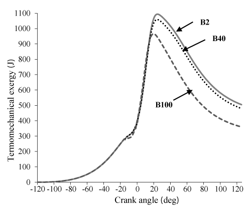
In a system, the thermomechanical availability A_thdenotes the maximum useful mechanical work educe able with the environment when the system reaches in thermal and mechanical equilibrium that its mass not allowed to react chemically or move with the surrounding atmosphere. The thermo-mechanical availability can be determined using the following formula [22]:

A th =( U U 0 )+ P 0 ( V V 0 ) T 0 ( S S 0 ) MathType@MTEF@5@5@+=feaaguart1ev2aaatCvAUfeBSjuyZL2yd9gzLbvyNv2CaerbuLwBLnhiov2DGi1BTfMBaeXatLxBI9gBaerbd9wDYLwzYbItLDharqqtubsr4rNCHbGeaGqiVu0Je9sqqrpepC0xbbL8F4rqqrFfpeea0xe9Lq=Jc9vqaqpepm0xbba9pwe9Q8fs0=yqaqpepae9pg0FirpepeKkFr0xfr=xfr=xb9adbaqaaeGaciGaaiaabeqaamaabaabaaGcbaaeaaaaaaaaa8qacaqGbbWdamaaBaaaleaapeGaaeiDaiaabIgaa8aabeaak8qacqGH9aqpdaqadaWdaeaapeGaaeyvaiabgkHiTiaabwfapaWaaSbaaSqaa8qacaaIWaaapaqabaaak8qacaGLOaGaayzkaaGaey4kaSIaaeiua8aadaWgaaWcbaWdbiaaicdaa8aabeaak8qadaqadaWdaeaapeGaaeOvaiabgkHiTiaabAfapaWaaSbaaSqaa8qacaaIWaaapaqabaaak8qacaGLOaGaayzkaaGaeyOeI0Iaaeiva8aadaWgaaWcbaWdbiaaicdaa8aabeaak8qadaqadaWdaeaapeGaae4uaiabgkHiTiaabofapaWaaSbaaSqaa8qacaaIWaaapaqabaaak8qacaGLOaGaayzkaaaaaa@505E@ (23)

where the subscript “0” represents the standard reference environmental state.

The Standard Entropy of each species is calculated using the following equation:

S i 0 = R i ( a 1 LnT+ a 2 T+ a 3 2 T 2 + a 4 3 T 3 + a 5 4 T 4 + a 7 ) MathType@MTEF@5@5@+=feaaguart1ev2aaatCvAUfeBSjuyZL2yd9gzLbvyNv2CaerbuLwBLnhiov2DGi1BTfMBaeXatLxBI9gBaerbd9wDYLwzYbItLDharqqtubsr4rNCHbGeaGqiVu0Je9sqqrpepC0xbbL8F4rqqrFfpeea0xe9Lq=Jc9vqaqpepm0xbba9pwe9Q8fs0=yqaqpepae9pg0FirpepeKkFr0xfr=xfr=xb9adbaqaaeGaciGaaiaabeqaamaabaabaaGcbaaeaaaaaaaaa8qacaqGtbWdamaaBaaaleaapeGaaeyAaaWdaeqaaOWaaWbaaSqabeaapeGaaGimaaaakiabg2da9iaabkfapaWaaSbaaSqaa8qacaqGPbaapaqabaGcpeGaaiikaiaabggapaWaaSbaaSqaa8qacaaIXaaapaqabaGcpeGaaeitaiaab6gacaqGubGaey4kaSIaaeyya8aadaWgaaWcbaWdbiaaikdaa8aabeaak8qacaqGubGaey4kaSYaaSaaa8aabaWdbiaabggapaWaaSbaaSqaa8qacaaIZaaapaqabaaakeaapeGaaGOmaaaacaqGubWdamaaCaaaleqabaWdbiaaikdaaaGccqGHRaWkdaWcaaWdaeaapeGaaeyya8aadaWgaaWcbaWdbiaaisdaa8aabeaaaOqaa8qacaaIZaaaaiaabsfapaWaaWbaaSqabeaapeGaaG4maaaakiabgUcaRmaalaaapaqaa8qacaqGHbWdamaaBaaaleaapeGaaGynaaWdaeqaaaGcbaWdbiaaisdaaaGaaeiva8aadaahaaWcbeqaa8qacaaI0aaaaOGaey4kaSIaaeyya8aadaWgaaWcbaWdbiaaiEdaa8aabeaak8qacaGGPaaaaa@5AA9@ (24)

Coefficients in the above equation for each species were collected from JANAF table [17]. The standard entropy at different pressures calculate as follows:

S i = S i 0 R i Ln( x i P P 0 ) MathType@MTEF@5@5@+=feaaguart1ev2aaatCvAUfeBSjuyZL2yd9gzLbvyNv2CaerbuLwBLnhiov2DGi1BTfMBaeXatLxBI9gBaerbd9wDYLwzYbItLDharqqtubsr4rNCHbGeaGqiVu0Je9sqqrpepC0xbbL8F4rqqrFfpeea0xe9Lq=Jc9vqaqpepm0xbba9pwe9Q8fs0=yqaqpepae9pg0FirpepeKkFr0xfr=xfr=xb9adbaqaaeGaciGaaiaabeqaamaabaabaaGcbaaeaaaaaaaaa8qacaqGtbWdamaaBaaaleaapeGaaeyAaaWdaeqaaOWdbiabg2da9iaabofapaWaaSbaaSqaa8qacaqGPbaapaqabaGcdaahaaWcbeqaa8qacaaIWaaaaOGaeyOeI0IaaeOua8aadaWgaaWcbaWdbiaabMgaa8aabeaak8qacaqGmbGaaeOBamaabmaapaqaa8qadaWcaaWdaeaapeGaaeiEa8aadaWgaaWcbaWdbiaabMgaa8aabeaak8qacaqGqbaapaqaa8qacaqGqbWdamaaBaaaleaapeGaaGimaaWdaeqaaaaaaOWdbiaawIcacaGLPaaaaaa@487C@ (25)

Finally, to calculate total entropy, the following equation is used

S= m i S i     MathType@MTEF@5@5@+=feaaguart1ev2aaatCvAUfeBSjuyZL2yd9gzLbvyNv2CaerbuLwBLnhiov2DGi1BTfMBaeXatLxBI9gBaerbd9wDYLwzYbItLDharqqtubsr4rNCHbGeaGqiVu0Je9sqqrpepC0xbbL8F4rqqrFfpeea0xe9Lq=Jc9vqaqpepm0xbba9pwe9Q8fs0=yqaqpepae9pg0FirpepeKkFr0xfr=xfr=xb9adbaqaaeGaciGaaiaabeqaamaabaabaaGcbaaeaaaaaaaaa8qacaqGtbGaeyypa0ZdamaavacabeWcbeqaaiaaygW7a0qaa8qacqGHris5aaGccaqGTbWdamaaBaaaleaapeGaaeyAaaWdaeqaaOWdbiaabofapaWaaSbaaSqaa8qacaqGPbaapaqabaGcpeGaaiiOaiaacckacaGGGcaaaa@438D@ (26)

where mi is mass of each specie. Sgen is the entropy generation per a cycle which can be given as follow [20]:

S gen =( S out S in )+ Q w T 0 + I T 0    MathType@MTEF@5@5@+=feaaguart1ev2aaatCvAUfeBSjuyZL2yd9gzLbvyNv2CaerbuLwBLnhiov2DGi1BTfMBaeXatLxBI9gBaerbd9wDYLwzYbItLDharqqtubsr4rNCHbGeaGqiVu0Je9sqqrpepC0xbbL8F4rqqrFfpeea0xe9Lq=Jc9vqaqpepm0xbba9pwe9Q8fs0=yqaqpepae9pg0FirpepeKkFr0xfr=xfr=xb9adbaqaaeGaciGaaiaabeqaamaabaabaaGcbaaeaaaaaaaaa8qacaqGtbWdamaaBaaaleaapeGaae4zaiaabwgacaqGUbaapaqabaGcpeGaeyypa0ZaaeWaa8aabaWdbiaabofapaWaaSbaaSqaa8qacaqGVbGaaeyDaiaabshaa8aabeaak8qacqGHsislcaqGtbWdamaaBaaaleaapeGaaeyAaiaab6gaa8aabeaaaOWdbiaawIcacaGLPaaacqGHRaWkdaWcaaWdaeaapeGaaeyua8aadaWgaaWcbaWdbiaabEhaa8aabeaaaOqaa8qacaqGubWdamaaBaaaleaapeGaaGimaaWdaeqaaaaak8qacqGHRaWkdaWcaaWdaeaapeGaaeysaaWdaeaapeGaaeiva8aadaWgaaWcbaWdbiaaicdaa8aabeaaaaGcpeGaaeiOaiaabckaaaa@50AB@ (27)

where s states gas entropy, Qw states the heat transfer to the cylinder walls, I is the total irreversibilities and T0 is the ambient temperature.

The first and second law efficiencies

Energy and exergy efficiencies are dimensionless performance measures of a device that uses thermal energy, such as an internal combustion engine, so these could be some of the best criteria to compare various engine working under different condition for example in different size or fulled with different source of energy such as biodiesel. The first law (or energy- based) efficiency and the second law efficiency (or exergy-based) is defined as equation (31) and (32) respectively.

η Ι = W m f LHV    MathType@MTEF@5@5@+=feaaguart1ev2aaatCvAUfeBSjuyZL2yd9gzLbvyNv2CaerbuLwBLnhiov2DGi1BTfMBaeXatLxBI9gBaerbd9wDYLwzYbItLDharqqtubsr4rNCHbGeaGqiVu0Je9sqqrpepC0xbbL8F4rqqrFfpeea0xe9Lq=Jc9vqaqpepm0xbba9pwe9Q8fs0=yqaqpepae9pg0FirpepeKkFr0xfr=xfr=xb9adbaqaaeGaciGaaiaabeqaamaabaabaaGcbaaccaaeaaaaaaaaa8qacqWF3oaApaWaaSbaaSqaa8qacqWFzoqsa8aabeaak8qacqGH9aqpdaWcaaWdaeaapeGaae4vaaWdaeaapeGaaeyBa8aadaWgaaWcbaWdbiaabAgaa8aabeaak8qacaqGmbGaaeisaiaabAfaaaGaaiiOaiaacckaaaa@42D7@ (28)

η ΙΙ = A w m f a fch      MathType@MTEF@5@5@+=feaaguart1ev2aaatCvAUfeBSjuyZL2yd9gzLbvyNv2CaerbuLwBLnhiov2DGi1BTfMBaeXatLxBI9gBaerbd9wDYLwzYbItLDharqqtubsr4rNCHbGeaGqiVu0Je9sqqrpepC0xbbL8F4rqqrFfpeea0xe9Lq=Jc9vqaqpepm0xbba9pwe9Q8fs0=yqaqpepae9pg0FirpepeKkFr0xfr=xfr=xb9adbaqaaeGaciGaaiaabeqaamaabaabaaGcbaaccaaeaaaaaaaaa8qacqWF3oaApaWaaSbaaSqaa8qacqWFzoqscqWFzoqsa8aabeaak8qacqGH9aqpdaWcaaWdaeaapeGaaeyqa8aadaWgaaWcbaWdbiaabEhaa8aabeaaaOqaa8qacaqGTbWdamaaBaaaleaapeGaaeOzaaWdaeqaaOWdbiaabggapaWaaSbaaSqaa8qacaqGMbGaae4yaiaabIgaa8aabeaaaaGcpeGaaiiOaiaacckacaGGGcGaaiiOaaaa@4961@ (29)

Results and discussion

The engine used in this study was direct injection diesel engine. The basic specif-ications of the engine are given in Table 1. All tests were conducted under full load and constant speed of 1200 rpm. In this study, the effect of the variation the concentration of biodiesel in the blend (i.e. 100%, 40%, 20% proportions by volume, derived from soybean oil) was investigated.

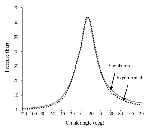
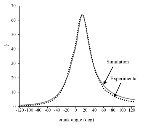
In Figures 1-3 the model is validated by comparing the diagram of the cylinder pressure and the result showed a good agreement. Similar to all zero dimens- ional models, the pick cylinder pressure is higher than the experimental result. This is the main disadvantage of zero dimensional models that originate from considered uniform temperature and uniform composition of charge throughout the cylinder. In this part of our study, the crank angle varies from-120 to 120 CA and its effects on exergy terms and related parameters will be investigated.

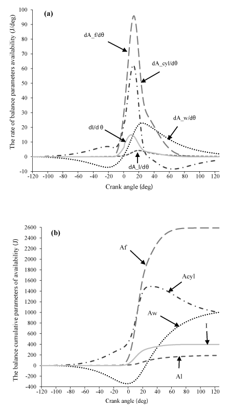
Application of the availability balance to the internal combustion engine Application of Eqs. (16)– (25) on a (diesel) engine cylinder is depicted in Fig. 4, showing the development of both rate and cumulative in-cylinder availability terms during an engine cycle.

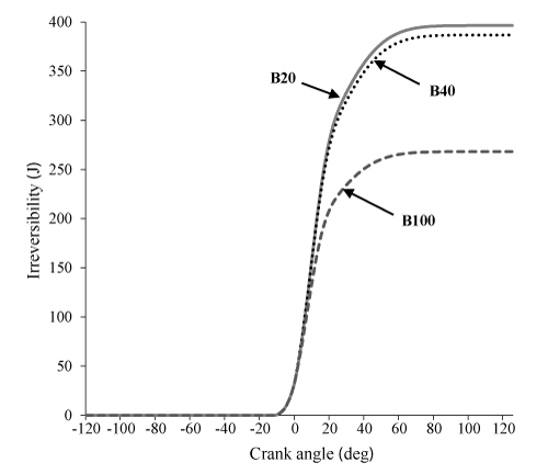
The availability of the cylinder contents (i.e. control volume availability) had an upward trend until the start of combustion, this might happen due to work done by the piston during the compression process. At the point the fuel injection starts, a small fall is observed in the control volume availability rate pattern. This is due to the ignition delay period and the simultaneous loss of heat for evaporation of the injected fuel. Similar result for DI diesel engine is gained by Abbasi et al. [15]. Before the start of combustion, the burned fuel availability is zero, start of combustion and the burning of fuel causes a considerable increase in dAf and Af, whereas with decrease in burned fuel, dAf decrease. Output availability from the cylinder associated with the indicated work is negative during compression and delay combustion, after these process, becomes positive with increasing piston displacement volume. Availability loss associated with the heat transfer to the cylinder walls will appeared during cycle, the compression and burning of fuel causes a considerable increase in pressure and temperature and, consequently, in cylinder availability and heat loss, when the pressure and temperature begin to fall during the expansion, there is also a fall in availability. The maximum availability loss with heat transfer occurred in combustion process, due to the maximum temperature and heat losses. I and dI in start of combustion increases due to increase in pressure and temperature. After combustion, decreasing pressure and temperature and, consequently, decreasing entropy and enthalpy, causes the decrease in the irreversibility [26] . Also, it can be observed in Figure 4, Af, AcyI, Aw, I, AI are the maximum values, respectively.

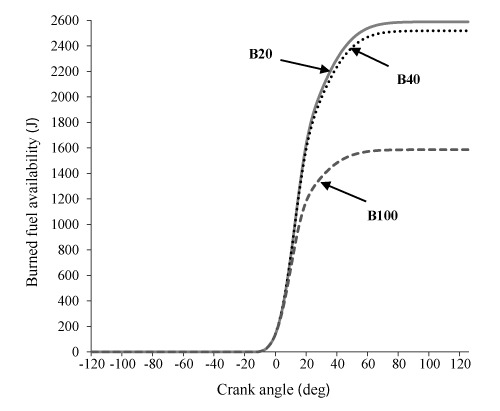
Figures 5-9 indicate the influence of the various blends (B20, B40, B100) on the parameters of availability balance. It can be observed in Figures. 5 and 6 that Af and I for the two cases of B20 and B40 is very close to each other, but much more than B100. This is due to the higher heating value of B20, B40 and B100, respectively which Resulting in significant differences in chemical exergy afch between B20 and B40 compared to B100.

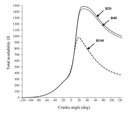
Figure 7 indicate that, total exergy of B20 is more than B40 and B100, respectively. This result can be explained by referring to eq. (16), that due to the significant contribution of burned fuel availability in exergy balance equation, total exergy is closely related to burned fuel availability.

Figure 8, show that, indicated work availability for three states are almost equal. It should be noted here that, an change in the pressure cylinder leads to a change in indicated work availability and because of it for B20 and B40 is closely to B100, indeed Aw is almost equal.

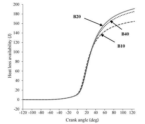
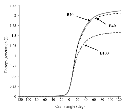
Figure 9 states that availability loss associated with the heat transfer for B20 and B40 is more from B100 which is issue of the increase in the combustion temperature in these two state. Figure 10 shows that an increase in percent biodiesel leads to a decrease in entropy. This happens due to increase of the combustion temperature, which leads to an increase in the heat loss and availability. Also, due to higher energy and entropy changes for B20 and B40, thermomechanical availability is more than B100. (Indeed the difference of B20 and B40 can be ignored, B100 has the lowest). It can be observed in Figure 11.

The first-law efficiency, second-law efficiency and the ratio of parameters of availability balance to burned fuel availability for the various blends of biodiesel are given in table 2.

Table 2 shows that 50.01% of the burned fuel availability of B100 is converted into indicated work availability, which is higher than the values of both states of B40 and B20 (respectively, 39.01% and 38.64). It can be concluded from higher oxygen content and improvement of combustion efficiency pure biodiesel. Also, a greater percentage of Af spent on availability loss associated with the heattransfer and irreversibility. This result can be explained by referring to increase in the proportion of biodiesel which leads to an increasing cetane number, decreasing ignition delay and accelerate auto ignition. It can be observed in table 2 that, the ratio of total exergy to burned fuel availability for pure biodiesel is less than two other states, which is issue increase of the ratio of Aw, I and AI for B100. In the end, first-law efficiency of B100 is higher than B40 and B20.

Conclusion

In this work, the influences of the various biodiesel blends are studied in a DI diesel engine on by the first and second laws of thermodynamics. For this purpose, a single zone thermodynamic model was used and tested favorably against experimental results. The results from energy and exergy analysis show that maximum values of parameters of availability balance are for Af, AcyI, Aw, I and AI, respectively. Comparisons between the different blends of biodiesel showed first and second-law efficiencies for pure biodiesel and exergy, indicated work availability, loss heat availability, burned fuel availability and irreversibility for B20 are higher than the other blends. Also a greater percentage of pure biodiesel is converted into availability loss asso-ciated with the heat transfer and indicated work availability.

Where W is the indicated work and Aw is output availability from the cylinder associated with the indicated work [23-25].

  1. Kannan G, Anand R (2012) Biodiesel as an alternative fuel for direct injection diesel engines: A review. Journal of renewable and Sustainable energy 4: 012703.  Link: https://bit.ly/3tpQjND
  2. Sapuan S, Masjuki H, Azlan A (1996) The use of palm oil as diesel fuel substitute. Proceedings of the Institution of Mechanical Engineers, Part A. Journal of Power and Energy 210: 47-53.
  3. Trukhanov AV, Darwish KA, Salem MM, Hemeda OM, Abdel  Ati MI, et al. (2021) Impact of the heat treatment conditions on crystal structre, morphology and magnetic properties evolution in BaM nanohexaferrites. J Alloys Compd 866: 158961. Link: https://bit.ly/3eDjRTD
  4. Thakur A, Sharma N, Bhatti M, Sharma M, Trukhanov AV, et al. (2020) Synthesis of barium ferrite nanoparticles using rhizome extract of Acorus Calamus: Characterization and its efficacy against different plant phytopathogenic fungi, Nano-Struct. Nano-Objects 24: 100599. Link: http://bit.ly/3eHysxk
  5. Trukhanov SV, Trukhanov AV, Vasil'ev AN, Maignan A, Szymczak  H (2007) Critical behavior of La0.825Sr0.175MnO2.912 anion-deficient manganite in the magnetic phase transition region. JETP Lett 85: 507-512. Link: https://bit.ly/3voThDL
  6. Flynn P, Hoag K, Kamel M, Primus R (1984) A new perspective on diesel engine evaluation based on second law analysis. SAE Technical Paper 0148-7191. Link: http://bit.ly/3rJyPLw
  7. Şahin Z, Durgun O (2008) Multi-zone combustion modeling for the prediction of diesel engine cycles and engine performance parameters. Applied Thermal Engineering 28: 2245-2256. Link: http://bit.ly/3tj1nfd
  8. Rakopoulos C, Giakoumis E (2006) Second-law analyses applied to internal combustion engines operation. Progress in Energy and Combustion science 32: 2-47. Link: http://bit.ly/30KUwPn
  9. Traupel W (1957) Reciprocating engine and turbine in internal combustion engineering. Proceedings of the international congress of combustion engines (CIMAC). Zurich: Switzerland.
  10. Patterson D, Van Wylen GJ (1963) A digital computer simulation for spark-ignited engine cycles. SAE Technical Paper 0148-7191. Link: http://bit.ly/3qP59eJ
  11. Caton JA (2000) A review of investigations using the second law of thermodynamics to study internal-combustion engines. SAE Technical Paper 0148-7191. Link: http://bit.ly/3tkK3GC
  12. Misra RD, Jena J, Murthy M (2013) Energy and exergy analyses of a CI engine fuelled with palm biodiesel based on experimental data. International Journal of Exergy 13: 124-39. Link: https://bit.ly/30K8264
  13. Caliskan H, Tat ME, Hepbasli A, Van Gerpen JH (2009) Exergy analysis of engines fuelled with biodiesel from high oleic soybeans based on experimental values. International Journal of Exergy 7: 20-36. Link: https://bit.ly/2NicOV7
  14. Azoumah Y, Blin J, Daho T (2009) Exergy efficiency applied for the performance optimization of a direct injection compression ignition (CI) engine using biofuels. Renewable Energy 34: 1494-500. Link: http://bit.ly/3eAuDKp
  15. Heywood  BJ (1988) Internal Combustion Engine Fundamentals. New York: McGraw Hill. Link: http://bit.ly/3vnmcrK
  16. Cengel YA, Boles MA (2002) Thermodynamics: an engineering approach. Sea 1000-8862.
  17. Ferguson C, Kirkpatrick A (2001) Internal combustion engines applied thermosciences.  John Wiley and Sons Inc.
  18. Woschni G (1967) A universally applicable equation for the instantaneous heat transfer coefficient in the internal combustion engine. SAE Technical paper 0148-7191. Link: http://bit.ly/3lfEsP4
  19. Miyamoto N, Chikahisa T, Murayama T, Sawyer R (1985) Description and analysis of diesel engine rate of combustion and performance using Wiebe's functions. SAE Technical16. Link: http://bit.ly/2PVnHgw
  20. Michael JM, Howard NS (2000) Fundamentals of Engineering Thermodynamics. New York: McGraw Hill.
  21. Burnside B (1997) Advanced Thermodynamics For Engineers. Proceedings of the Institution of Mechanical Engineers 211: 357.
  22. Amjad A, Saray RK, Mahmoudi S, Rahimi A (2011) Availability analysis of n-heptane and natural gas blends combustion in HCCI engines. Energy 36:  6900-6999. Link: http://bit.ly/2OT2i7c
  23. Sezer I (2008) Application of exergy analysis to spark ignition engine cycle. PhD dissertation, Karadeniz Technical University, Trabzon, Turkey.
  24. Sezer İ, Bilgin A (2013) Effects of charge properties on exergy balance in spark ignition engines. Fuel 112: 523-230. Link: https://bit.ly/3cLlOuT
  25. Zhang S (2002) The second law analysis of a spark ignition engine fueled with compressed natural gas. Link: http://bit.ly/2OU5Fe0
  26. Alkidas A (1988) The application of availability and energy balances to a diesel engine. J Eng Gas Turbines Power 110: 462-469. Link: http://bit.ly/2OotE5v
© 2020 Habibian S, et al. This is an open-ampcess article distributed under the terms of the Creative Commons Attribution License, which permits unrestricted use, distribution, and reproduction in any medium, provided the original author and source are credited.
 

Help ?