Annals of Limnology and Oceanography
An Exploratory Modelling Study on Late Pleistocene Mega-Tsunamis Triggered by Giant Submarine Landslides in the Mediterranean
JM Abril and Raúl Periáñez*
Cite this as
Abril JM, Periáñez R (2017) An Exploratory Modelling Study on Late Pleistocene Mega-Tsunamis Triggered By Giant Submarine Landslides in the Mediterranean. Ann Limnol Oceanogr 2(1): 007-024. DOI: 10.17352/alo.000005Gigantic submarine landslides are among the most energetic events on the Earth surface. During the Late Pleistocene the Mediterranean Sea was the scenario of a 9 number of such events, some of whose geological fingerprints are the 500 km3 mass transport deposit SL2 at the Nile delta fan (dated at ca. 110 ka BP) and the Herodotus Basing Megaturbidite (HBM, a 400 km3 deposit dated at ca. 27.1 ka BP). This paper presents an exploratory study on the tsunamigenic potential of these slides by using a numerical model based on the 2D depth-averaged non-linear barotropic shallow water equations. The sliding mass is modelled both as a rigid block with a prescribed motion and as a viscous flow layer. The 26 km3 debris flow BIG’95 scenario (at the Ebro continental slope, 11.5 ka BP) served for model com-parison against independent modelling works. Based upon the available geologicalstudies, several source scenarios have been modelled. Our results show that the generated tsunamis would have had up to hundred fold the peak energy of some extreme historical ones, such as the 1755 Lisbon tsunami. Thus, the HBM tsunami could have reached peak energies over one hundred Megatons, producing runups over 50 m height along some 1300 km2 of shoreline in the eastern Mediterranean.
The study also comprises their propagation pattern, their impacts along the former shoreline and their energy partitioning. The highest tsunami energies were associated to thick landslides at shallow depths, with high slope angles and within a gulf geometry.
Introduction
The Lisbon earthquake of November 1st, 1755, triggered a transoceanic tsunami that hit the coastal areas of Spain, Morocco and Portugal, with its further reaches at Ireland, England and the Caribbean. Historical accounts report on runups over 10 meters at C´adiz and St Vincent Cape. The energy released by this tsunami was of ∼ 3.5 × 10¹⁵ J (∼ 0.84 Megatons, as estimated by the initial Okada’s deformation, after Abril et al., 2013) [1]. The December 26th, 2004 Indian Ocean Tsunami released an energy of 5.39×10¹⁵ J and encompassed the entire world ocean with maximum computed runups over 9 m at the shore of Thailand [2]. Some ancient giant landslides are among the most energetic events on Earth [3], and they may have triggered extreme mega tsunamis, exceeding those induced by mega-thrust earthquakes such as the historical ones reported above [4].
Submarine landslides consist of blocks that slide and bounce, eroding material at its passage, promoting secondary slides and increasing fragmentation and selective deposition before eventual transition to debris flows and turbidity currents; and they have occurred along most continental margins and along several volcano flanks [4]. The partitioning of the gravitational energy released by a submarine landslide takes place into the two main reservoirs of the solid earth (friction and seismic waves) and the ocean (friction and gravity waves). The large variety of failure types and rheologies associated with submarine landslides implies a considerable uncertainty in determining the efficiency of tsunami generation [5,6]. The fraction of energy transferred to water waves can range essentially from zero to about 50% as a practical upper limit [3].
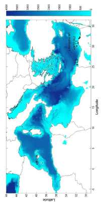
Improvements in swath mapping and geophysical techniques have allowed identifying a large number of submarine landslide deposits over the Mediterranean Sea (for a short summary see Papadopoulos et al.) [7]. Urgeles and Camerlenghi [8] published a review study on trigger mechanisms, dynamics and frequency-magnitude distribution of submarine landslides in the Mediterranean Sea. Cita et al. and Cita and Rimoldi [9,10] provided empirical evidence of a 10-20 m thick megaturbidite in the Ionian Abyssal Plain with an estimated volume of at least 11 km3 (re-evaluated as 65 km3 by Hieke and Werner, 2000) [11] and most likely being displaced from the Sirte Gulf, in the African shelf [12]. This landslide, evolving towards a giant turbidity current, was isochronous with the Minoan Santorini eruption, according to Cita et al. [9]. A modelling study on the tsunami possibly triggered by this submarine landslide is included in Peri´a˜nez and Abril [13]. In the western Mediterranean, the BIG’95 mass wasting event, with a volume of 26 km3 and dated at ca. 11.5 ka BP [14], may have triggered a tsunami [15]. Rothwell et al. [16] reported empirical evidence of a megaturbidite in the Balearic Abyssal Plain (the Balearic megaturbidite -BMT-) with a very large volume, of 500 − 600 km3. The mass wasting event that originated the megaturbidite, dated at ca. 22 ka BP, was likely located in the northern parts of the basin [17], although a well-defined source area still remains 70 unidentified. In the Herodotus Basin, a megaturbidite (HBM) dated at ca. 27.1 ka BP has been described by Rothwell et al. and Reeder et al. [18,19]. It covers an area of approximately 40000 km2 below the 3000 m isobath with an estimated total volume of 400 km3. Garziglia et al. [20] identified several mass-transport deposits (MTD) on the Rosetta province (NW Nile Delta, Egyptian margin). The largest one, labelled as MTD-SL2, with a total volume of ∼ 500 km3 is dated at 110 ka BP. Concerning the potential causal processes, as discussed in the above references, the triggering mechanism could have been a combination of low sea level, sediment oversupply, over-steeping of the shelf/slope, presence of gas and seismic activity. This paper is aimed to conduct an exploratory modelling study on the tsunamis that may have been triggered by the giant mass wasting events of BIG’95, HBM and MTD-SL2, for which possible source areas have been identified (Figure 1).
A statistical analysis for 160 landslide scars in the salt, fluvial and glacial portions of the U.S. mid-Atlantic margin, with volumes ranging from 10−3 up to 40 km3, has been published by ten Brink et al. [21]. They found that landslide volume increases almost linearly with area, which allows to infer that most landslides on the margin must be translational, failing along depositional layer boundaries separating units of similar thickness, and having low shear strength. Their results also suggested that slope destabilization can occur simultaneously within the area affected by horizontal ground shaking, and does not propagate from one or a few nucleating points. The physics of these mass flows can be divided into a triggering with break-up phase, flow and final deposition [22]. The approach of a submarine landslide moving as a single rigid body has often 92 been used for modelling giant events, such as the 165 km3 Currituck landslide [23], the 1200 km3 Brunei Slide [24], and the 3900 km3 Storegga slide [25], among others. Papadopoulos et al. [26], introduced a layered sediment structure instead of conventional rigid-body. Other modelling approaches are based upon the principles of the fluid dynamics. Thus, Fine et al. [27] treated the 1929 Grand Banks landslide (200 km3) as a liquefaction flow by modelling the slide as a viscous, in compressible fluid layer. De Blasio et al. [22] presented three different flow models for slides and debris flows in over consolidated clay materials: a viscoplastic (Bingham) fluid model, a viscoplastic fluid with interspersed solid blocks, and a viscoplastic model with yield strength increasing with depth. They found that the pure Bingham model performed better when applied to the Ormen Lange sub-region in the Storegga slide. The BIG’95 debris flow has been successfully modelled as a Bingham fluid with interspersed solid blocks [28,29].
Our purpose is not to simulate the entire motion and transformation of the studied mass wasting events, but to consider only their initial stages responsible for the generation of the tsunami waves. Thus, in this paper the Harbitz’s formalism [25] for a solid block has been adopted for modelling the landslide tsunamis, due to its simplicity, robustness, its proved use, and to the lack of field data for runups, which does not justify the use of more complex models. The modelling approach that consider the slide as a viscous, incompressible fluid layer [27] has also been applied to better illuminate the slide kinematics at the initial stages. The combination of both approaches served to discuss the range of uncertainty involved in the kinematics of the slides, and to define the sensitivity tests. The scenario of BIG’95 also served for model inter-comparison (in terms of the generated tsunami) of the present approach with the one using a Bingham fluid with interspersed solid blocks [15,28,29].
Due to the short length scale of landslide thickness variations relative to the water depth, frequency dispersion is normally more pronounced for landslide tsunamis. This makes its numerical modelling more complex [23,30,31]. Nevertheless, frequency dispersion may be of little importance for waves generated by the giant submarine landslides moving at small Froude numbers, as for the Storegga Slide tsunami [23,32,33,]. Taking into account the large volumes of the studied landslides, of several hundreds of km3, the selected modelling approach in the present work is based on the 2D depth averaged non linear barotropic shallow water equations. The numerical model has been previously applied to a wide set of tsunamis triggered by different mechanisms, including landslides [1,13,34,35], and it is briefly described in Section 2. Similar models have been widely applied to simulate tsunami propagation, independently of the origin of the tsunami. For instance, Alasset et al. (2006) and Sahal (2009) studied the 2003 Algeria tsunami. Models were applied to the 1755 Lisbon tsunami, among many others, by Baptista et al. (2003), Barkan et al. (2009) and Lima et al. (2010). Roger and H´ebert (2008) simulated the 1856 Algeria tsunami and tsunami hazard in the Caribbean Sea was evaluated by Harbitz et al. (2012). The 2004 Indian Ocean tsunami was studied, for instance, by Ioualalen et al. 2010. As a final example, tsunamis generated by volcanic eruptions were simulated by Choi et al. (2003) and Novikova et al. (2011).
This work provides an exploratory study on the generation, propagation and effects of giant tsunamis in the Mediterranean Sea. Results are expected to be of interest for improving our present level of knowledge on the behavior of marine systems under these extreme events, to identify the areas that could have suffered the highest impacts (and then perhaps being able to preserve some geological fingerprints)and to identify factors affecting the tsunami peak energy.
Model Description
Landslide description
For the three studied mass wasting events (BIG’95, MTD-SL2 and HBM) geological studies have allowed the identification of the landslide sources in precise areas of the continental shelves/slopes and with constrained geometries for the slides and their displacements.
These events introduce changes in the bathymetry of the source and depositional areas over which the subsequent geological history progresses. As a practical approach, the slides will be superposed onto the present-day bathymetry of the source area, where the scars and flanks allow to reasonably accommodate the simplified shape of the slides proposed by Harbitz [25], a box of length L, width B and maximum thickness ∆h, and with an exponential smoothing over a distance S in the front and rear and B/2 on the flanks. The resulting volume is V = 0.90B∆h(L + 0.90S). The slide defines a local height, as a mathematical function of spatial coordinates that superposes to present day bathymetry and displaces over it with a prescribed motion. The sea level at the date of each event has been simulated by an overall and uniform correction to the present water depths, estimated from eustatic sea levels by Pillans et al. [36].
The geometrical definition of the Harbitz’s slide is a crude approach, and model results will not be significantly improved by applying further refinements or corrections in the present day bathymetry of the source areas. These last corrections are kept to a minimum and resolved by a simple routine in the software, to avoid that in some cases a small fraction at the rear of the Harbitz’s slide exceeds the water depth.
The motion of the slides can be known after solving the governing dynamic equations [3,28]. Here we adopt the approach by Harbitz [25], in which the maximum velocity, Umax, is estimated as a function of the slope, the average thickness of the slide, its density, the density of turbidity currents and the friction and drag coefficients. Its value strongly depends on the estimation of the Coulomb friction coefficient, µ, within an acceptable range, but it is also subjected to the following restrictions: i) consistency with the energy balance; ii) it should not exceed maximum observed values. As some reference values, the following ones are found in scientific literature: 17-28 m/s (1929 Grand Banks landslide, Fine et al.,) [27], 27 m/s (1918 Monoa Passage tsunami) [37], 35 m/s (1998 Papua New Guinea tsunami) [38], 20 and 50 m/s (BIG’95 slide block and debris flow) [28], 20-50 m/s [25], and 60 m/s [39]. Here, as a practical pproach, µ has been initially fixed as the 95 % of its value for the static limit, being subjected to sensitivity tests; and 50 m/s has been adopted as the upper limit for Umax. Mathematical details are provided in Appendix A.
Sensitivity tests have been carried out for the maximum velocity and run-out distance.
The slide flowing as a viscous, incompressible fluid layer
The model by Fine et al. [27] has been adopted to constrain better the slide kinematics. 183 The initial shape and position of the slide is defined as in the previous case (the Harbitz’s 184 approach). The slide then moves spontaneously downslope as a viscous, incompressible fluid layer, forced by the reduced gravity. The governing equations and the estimation of parameter values appear in Appendix B. The model has been run over typical time intervals of 50 minutes to get a description of the initial stage of the mass wasting event. The outputs are the dynamical shape and position of the slide and the thickness and speed of each differential volume within it. From these data, the position and velocity of the center of gravity of the slide have been computed as a function of time. This provides a reference for comparison with the more simple and straightforward kinematics derived from the rigid block approach (Appendix A).
Sensitivity tests have been conducted for the viscosity and the reduced gravity.
The model choice is justified since it was able to provide a good description of the flow velocities for the 1929 Grand Banks landslide [27], which is our present interest. The initial stage of the mass wasting event governs the generation of tsunami waves. At this stage, the deformation of the slide still is moderate, and its kinematics can provide a good proxy for a rigid-block model, as it will be shown with the BIG’95 event.
Tsunami generation and propagation
The slide model is coupled with the tsunami propagation model. This model is based on a modified version of the 2D depth-averaged nonlinear barotropic shallow water equations, which describe the propagation of surface shallow water gravity waves [13,34,40]:
![]()
![]()
where u and v are the depth averaged water velocities along the x and y axis, h is the depth of water below the mean sea level, ζ is the displacement of the water surface above the mean sea level measured upwards, D = h + ζ is the total water depth, Ω is the Coriolis parameter (Ω = 2w sinλ, where w is the Earth rotational angular velocity and λ is latitude), ρw is water density and A is the horizontal eddy viscosity. τu and τv are friction stresses that have been written in terms of a quadratic law:

Where kf is the bed friction coefficient. ur and vr are the two components of the r velocity between water and the slide. Thus, kinetic energy is transferred from the moving bottom to the water column. Values of kf = 0.0025 and A = 10 m2/s have proved their used in previous works [13,34,35] .
The continuity equation (Eq. 1) has also been modified. Thus, hs denotes the instantaneous sea surface elevation caused by the passage of the underwater landslide. This term is the link between the landslide model and the tsunami propagation model. The relation between hs and the local thickness of the slide Hs at the sea bottom is calculated by means of a transfer function according to:
![]()
with
![]()
Where L is the length of the slide. If the transfer function is not used, then ∂hs/∂t = ∂Hs/∂t, which is a good approximation only if the slide length is much larger than the water depth. Using the transfer function 1/cosh ψ attributes different potential to landslides of different L and moving at different ocean depths. As a consequence, a shallow water slide will have a higher capacity of exciting waves (ψ → 0 and thus than if it moves in the deep ocean ( 0 and ∂hs/∂t «∂Hs/∂t thus). Details are presented in Tinti et al. [41].
Equations in the model are solved using explicit finite difference schemes [40] with second order accuracy. In particular, the MSOU (Monotonic Second Order Upstream) is used for the advective non-linear terms in the momentum equations.
The computational domain extends from 6oW to 36.5oE and from 29.5oN to 46oN. Water depths have been obtained from the ETOPO digital bathymetry, available online (https://www.ngdc.noaa.gov/mgg/global/global.html), with a resolution of 1 minute of arc both in longitude and latitude. Due to the Courant-Friedrichs-Lewy (CFL) stability condition [40], time step for model integration was fixed as ∆t = 2 s. For the BIG’95 simulation, a subdomain with a spatial resolution of 30 second of arc (from GEBCO-08 bathymetry) and ∆t = 1 s has been used. The sea level has been corrected in each simulated event, as explained above.
Boundary conditions are required to solve the model equations. A gravity wave radi ation condition [42] is used for sea surface elevation along open bound aries, which is implemented in an implicit form. This condition avoids artificial wave reflections in open boundaries. A flood/dry algorithm is required since when the tsunami reaches the coast new wet or dry grid cells may be generated due to run-up or rundown.
The numerical scheme described in Kampf [43] has been adopted. A FORTRAN246 code was written by the authors to implement all equations. The model has resulted to 247 be quite robust when applied to some extreme scenarios, as the Zanclean flood of the 248 Mediterranean [44].
In the case of tsunamis generated by submarine earthquakes, the tsunami propagation model has been validated in Peri´a˜nez and Abril [34]. The coupling of the slide model to the tsunami propagation model has been validated in Peri´a˜nez and Abril [13]. In both cases, model results have been tested for past events for which historical data and/or previous simulations exist. Details can be obtained from both references.
Energy calculation
The shift in the potential gravitational energy, ∆Ep, associated to the change in depth undergone by the gravity center of the slide, ∆hg, can be estimated as
∆Ep = V (ρs − ρw)g∆hg (7)
Where ρs is the material bulk density, ρw is water density and g the acceleration of gravity. Only a fraction of this energy is transferred to the tsunami.
At any given time, the energy of the moving water (the tsunami) can be computed as the summation over the whole domain, Ω, of its kinetic (EK,w) and gravitational potential (EP,w) energies:
![]()
![]()
The vertical velocity has been neglected since its contribution to EK,w is typically two orders of magnitude lower than that of the horizontal velocities.
The 11.5 ka BP BIG’95 debris flow. Model intercomparison
Geological features and definition of the landslide setup: Lastras et al. [14] reported seafloor imagery from the BIG’95, a 26 km3 debris flow deposit covering 2000 km2 of the Ebro continental slope and base slope. The event is dated at ca. 11.5 ka BP. The source (delimited by the main scars) and depositional areas are shown in Figure 2, along with the present bathymetry. Blocks of cohesive sediment are found on the proximal and intermediate depositional areas (15-20 km run-out), while only the loose fraction reached the distal depositional area (110 km run-out). Lastras et al. [28] developed a conceptual and numerical model discerning these two main sediment phases: the loose fraction (9 km3), treated as a Bingham fluid that reached 50 m/s in speed after 8 minutes, and a perfect rigid block (17 km3) that reached a maximum velocity of 20 m/s and stopped after 73 minutes. More recently, and based upon this model, Iglesias et al. [15] published a numerical simulation of the BIG’95 submarine landslide-generated tsunami, which will serve here for inter-comparison purposes. Løvholt et al. [29] simulated the BIG’95 tsunami using a dispersive tsunami model which produced larger waves than the previous modelling study.
As most of the energy transfer to ocean gravity waves takes place during the landslide stage, in our simplified modelling approach we will consider that the whole 26 km3 of sediments move as a Harbitz’s slide with a maximum velocity of 30 m/s (close to the mean quadratic velocity of both phases). From the detailed map by Lastras et al. [14]-their Figure 2,- a value of B = 18.0 km can be selected for the width of the slide, with its corresponding lateral smoothing. The height of the headwall defined by the main scar is as much 200 m, and of 50-100 m for the secondary ones. Thus, the slide geometry has been completed with a value of ∆h = 156 m, a length L = 8.5 km and a smoothing distance S = 2.0 km. The direction of the movement (130 degrees clockwise from the north) can be also inferred from this map. An effective run-out distance of 20.2 km has been selected, divided into two transects, of 7.2 km and about 4o slope, and of 13.0 km and 1o slope. After imposing the previous maximum velocity, the time parameters arise from Eqs. 13, 15, and 16. The involved parameters are summarized in Table 1. The mean sea level at 11.5 ka BP was about -50 m (negative values mean sea levels below the present day one), from Pillans et al. [36].
Model results
A summary of model results is presented in Figure 3. The snapshots of water elevations 18 and 27 minutes after the start of the landslide can be compared with those published by Iglesias et al. [15]. Details in the near field depend on the source definition but, overall, the shape of the wave front, the arrival times and maximum amplitudes are in reasonable good agreement with previous results. Time series of water elevations at some selected sites (bullets 1 to 6 in Figure 3) are provided in Figure S-1 (in electronic supplementary material), for comparison. They correspond to a second modelling exercise using the present sea level, as in Iglesias et al. [15]). A wave amplitude of 10 m is registered at the initial slide front, and it is over 8.9 m in NW Eivissa, 6 m in western Mallorca and Santa Pon¸ca, and 2.6 m at Can Pastilla (in Palma Bay). Main discrepancies appear in the continental coastline of Castell´o where the negative polarity of the wave is well reproduced, but its maximum amplitude, 3.6 m, is smaller than the one in the model by Iglesias et al. [15]. It is worth noting that our results, with a fully non-linear model, follow the typical pattern of sub-critical landslides, with a characteristic, symmetric sickle-shaped surface elevation followed by a surface depression [33]. Despite the details in the near field, the present modelling approach is able to provide a reasonable general view of the tsunamigenic potential of the studied mass wasting events, their propagation patterns and it is also able to estimate currents and wave amplitudes. Runups in the flooded areas can be obtained as well.
Time series of kinetic and potential energy over the whole domain have been generated. The global peak energy is 8.4 × 10¹⁴ J (0.2 Megatons). When compared with the gap of gravitational potential energy in the prescribed motion (3.4 × 10¹⁶ J, from Eq. 7), the conversion factor (referred to the peak) is 2.8%, within the range of usual values found in literature (e.g. 0.1% to 15% in Harbitz et al.,) [33]. A more detailed discussion on the peak value, partitioning and behavior of energy in the landslide-generated tsunamis will be presented further below.
The 110 ka BP SL-2 mass-transport deposit in nile delta
Geological features and definition of the landslide setup: The Messinian desiccation event led to the deposition of salt and anhydrite throughout the Mediterranean basin. Thick units of Plio-Quaternary sediment, transported offshore by the Nile River, covered then the ductile evaporitic layers, triggering some giant gravity driven salt tectonics [45,46].
Garziglia et al. [20] identified seven mass-transport deposits on the Western province, north of Rosetta Canyon, downstream of imbricate scars (30.0oE, 31.5oN). The estimated volumes of these deposits range from 3 to 500 km3, mean thicknesses from 11 to 77 m and run-out distances from 18 to 150 km. Among them, SL2 is the largest one, covering an area of 5000 km2, with a mean thickness of 70 m, and a total volume of 500 km3.
The reported run-out, in the SE to NW direction, is 150 km (from the head scars to the most distal part of the MTD). The authors provided detailed maps showing the areal distribution of the mass-transport deposit SL2, and the position of the head scars. Based on the study of planktonic foraminifera and sapropel markers, they estimated that the deposition of SL2 occurred between 117 and 105 ka BP. This time interval corresponds to a period of rapid change in the Mediterranean sea-level [20,36], which dropped from -10 to -40 m, with a minimum about -45 m at 110 ka BP. For this study, a value of -25 m will be adopted. Concerning the potential causal processes, Garziglia et al. [20], discussed that the presence of gas in the sediment and earthquake shaking may have concurred to trigger large-scale failures on the low slope angles (1o-2o) of the Rosetta area.
The high resolution bathymetric map of Garziglia et al. [20], shows a rectangular depression running NW of the scars segments A and B (at the isobath of 200 m), and following the Rosetta canyon. It has a mean width of 28 km, and there are signs of a noticeable remobilization of sediments in both flanks. At the isobath of 1400 m, it connects with the SL2 MTD (Figure 2). These features also contain the effects of other more recent mass wasting deposits, but they allow defining the main parameters for a Harbitz’s slide.
The MTD-SL2 deposit is dominated by a transparent facies, but it includes a head ward unit characterized by extensional rotated blocks, and an intermediate unit characterized by rafted blocks evolving downslope into an entirely internally disrupted unit [20]. After these authors, the mobility of the initially failed mass must have been sufficiently high to induce disruption and intense remoulding of its constitutive material.
Although new materials may have been incorporated during the slide displacement, in our modelling approach the 500 km3 of sediments are allocated within the source area, in a 30 km wide slide (with an exponential lateral smoothing), with a length of 40.9 km (the mean distance between isobaths of 400 and 1400 m) and a smoothing distance of 6 km at the front and rear. The maximum height required to produce a 500 km3 slide with the mentioned geometry is 400 m. The slide moves down a slope of 1o that reduces to 0.75o after 60 km. The run-out distance must be estimated from the initial and final position of the center of gravity. The precise data is not available for SL2, but a plausible value of 76 km has been adopted, based on the distribution maps by Garziglia et al. [20] and subjected to sensitivity tests. The direction of the displacement is also defined by the geometry of the slide.
Under the approach of a rigid block, the maximum velocities at the two slopes can be estimated from the Harbitz’s formulae adopting a Coulomb friction coefficient close (95%) to its upper limit (see Appendix A). The resulting values (44.3 and 38.7 m/s) are acceptable within the expected range of velocities (see references in section 2). A summary of the SL2 slide parameters is presented in Table 1, and its representation on the bathymetric map appears in Figure 2. This constitutes the reference run N0. Under the prescribed motion, the Froude number (estimated at the position of the slide centroid) increases from zero up to a peak value of 0.37 and then declines, being consistent with the simplification of using a non-dispersive model.
Sensitivity tests have been conducted for the main sources of uncertainty in the slide and kinematic definitions (within the model of a rigid block): i) Estimation of Umax, by using µ = 0.90 µmax (run N1) and µ =0.97 µmax (run N2); for N1 the upper limit of Umax must be used. ii) The total run-out distance, by increasing (N3) and reducing (N4) its nominal value (on the basis of run N0) by 15 km. In the last case the model operates with a single slope angle, and the time of occurrence for the maximum velocity (and thus, the initial acceleration) can be modified by varying the first run-out distance, as done with runs N5 and N6. A summary of parameters appears in Table 1, and the corresponding 384 time series for the velocity of the slide are presented in Figure S-2 (electronic supplementary material).
Kinematics from the viscous landslide model
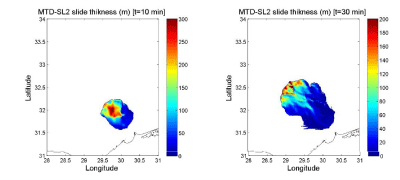
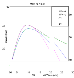
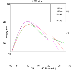
Figure 4 shows the snapshots with computed thickness for the MTD-SL2 slide as it flows as a viscous, incompressible fluid layer. The governing equations and parameter values are provided in Appendix B. The spatial resolution is 30 seconds of arc, and the time step 1 s. The slide spontaneously moves downslope with its center of gravity following closely the direction defined by an angle of 322 degrees (measured clockwise from the North). After 10 minutes, the slide still maintains an almost rectangular shape, with thickness over 250 m. The computed velocities for its center of gravity appear in Figure 5. By using the same entry parameter values as Fine et al. [27] -see Appendix B-, the velocity reaches a maximum value of 53.8 m/s after 11.5 minutes. As a “no stop condition” was applied to the downslope slide motion, the computed velocities slowly decrease after their maximum. It is worth noting that this stage of the slide movement has a lower effect in the generation of the tsunami waves.
It is well known that viscosity plays a minor role [22]. Thus, increasing/decreasing the nominal value of the viscosity by a 25% produced negligible changes in the computed velocity for the center of gravity (not shown). When using a lower value for the density of the sediments (1700 kg m−3), the reduced gravity decreased by a 19% and the computed maximum speed was 48.5 m/s. It was attained after 12.5 404 minutes (Figure 5). The same Figure plots the analytical functions generated with the two slope kinematic model (Eqs. 12 to 16 in Appendix A, with Umax,1 = Umax,2) in such a way that they fit the initial stage of the motion until attaining the maximum speed value, 407 and to complete the total runout of 75 km (curves A1 and A2 in Figure 5).
In Figure S-2 most of the curves compare well with the computed ones shown in Figure 5, both in terms of maximum speed and time of its occurrence. Curve N5 can be considered as a numerical experiment that will serve to explore the effect of higher initial accelerations, and curve N2 provides a more conservative estimation of the tsunamigenic potential of this submarine landslide. Curve A2 in Figure 5 serves to define the run N-A2 in Table 1. The whole set will provide a reasonable basis for studying the model sensitivity to the prescribed kinematics.
Model results
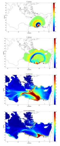
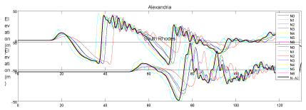
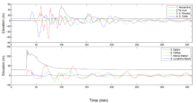
Results on tsunami propagation for run N0 are shown in Figure 6. A positive wave, up to 150 m high at the front position, propagates in the direction of the slide displacement and spreads in a semi-circular wave-front. A huge depression appears at the rear, inducing a water inflow into it, which finally produces a second positive wave in its former position.
At the former coastline of Alexandria water recedes during 20 minutes, decreasing sea level by 40 m. Then, in less than 4 minutes, a wave over 30 m high hits the coast (Figure 7).
Waves over 20 m high cross the Herodotus Basin and gain amplitude when arriving to the Cretan-Rhodes arc and SW Turkey. Tsunami amplitudes are also high along the shallow coastal areas from Northern Libya to Israel. At Marsa Matruh area (North Libya), the tsunami arrives after 30 minutes with a positive wave over 20 m, which is followed by a water drop that dries out the area for 10 minutes (Figure 7). At Tel Aviv area, the tsunami amplitude does not exceed 5 m. Time series of elevations at other selected sites are also presented in Figure 7. Water currents are very high, exceeding 10 m/s, in the source area and westward along the coastline of north Egypt and Libya.
The peak tsunami energy is 7.5 × 10¹⁷ J (178 Megatons), which is almost 15% of the available potential gravitational energy in the prescribed motion (Table 1). Most of this energy dissipates in the areas where high current amplitudes occur (Figure 6).
Sensitivity tests show that the tsunami peak energy is primarily governed by the maximum velocity of the slide. Thus, for runs N0, N4, N5, N6, with the same Umax= 44.3 m/s, the peak energy is 178 ± 2 Mt (mean value and standard deviation). For runs N1 (Umax= 50 m/s) and N2 (Umax= 34.2 m/s) the peak energy is 221 Mt and 100 Mt, respectively. For run N-A2, with Umax= 48.2 m/s, the peak energy is 209 Mt.
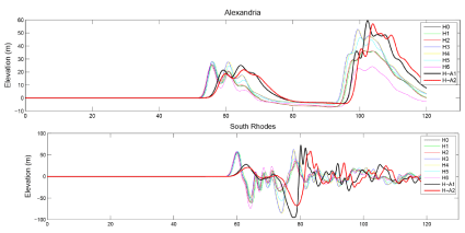
Figures 8 and S-3 (electronic supplementary material) show the computed time series of water elevations for all the tsunamis at four selected locations. At Alexandria (Figure 8) and Salˆum (Figure S-3), in northern Africa, the general pattern of the first wave is well preserved, being the major difference the arrival time, related with the time of occurrence of Umax. At South Rhodes (Figure 8), the same effect is observed, but superimposed to a variation in maximum wave amplitudes, with higher and similar values (∼ 48 m) for N1, N5 and N6, intermediate values (∼ 40 m) for N0 and N3, and lower (30 m) for run N2 (the less energetic one). Similarly, at Fethije (SW Turkey), and as shown in Figure S-3, the same delay effect is observed, while variations in amplitudes are more noticeable in the first receding wave. The computed time series of water elevations with tsunami N-A2, which uses the kinematics from the viscous slide model, fall within the trend shown for other tsunamis. Due to the strong directionality in the tsunami propagation (Figure 6), it is expected that major differences in the impacts on the coastal areas due to a higher peak energy will occur along such direction. This explains the relatively limited differences found in the locations included in the previous Figures, but they are much larger in South Crete (Figure S-3), where the first receding wave reaches -48 m, -36.7 m and -20 m for tsunamis N1, N0 and N3, respectively.
The 27.1 ka BP Herodotus Basin Megaturbidite
Geological features and definition of the landslide setup: The Herodotus Basin Megaturbidite (HBM) covers an area of approximately 40000 km2 below the 3000 m isobath, with thickness ranging from 10 to 20 m, and with an estimated total volume of 400 km3 [18,19,]. Reeder et al. [19] identified a funnel-shaped marginal embayment at the Gulf of Salˆum as the most likely source area. This could account for some 300 km3 of sediments, and the additional material may have been derived from synchronous failures on other parts of the Libyan/Egyptian shelf and from large-scale erosion due to the giant turbidity currents. The bathymetry of the source area shows no evidence of a slide scar, which may suggest that there have been more recent collapses masking the earlier scarp [19]. Based on radiocarbon 14C, it has been dated at approximately 27.1 ka calendar years BP, when the Mediterranean Sea level was about -75 m [36]. The collapse of the Gulf of Salˆum region may have been initialized as a submarine landslide that evolved towards a debris flow and turbidity current [19]. After these authors, the triggering mechanism could have been a combination of low sea level, sediment oversupply, over steepening of the shelf/slope and seismic activity.
The collapsed area in the Gulf of Salˆum is about 42 km wide at its shallowest part and it progressively narrows towards a canyon that runs down the continental slope. The selected Harbitz’s slide to fit this area is B = 36 km wide, and L = 26.4 km long. It extends approximately between 400 m and 1400 m water depth. The smoothing distance, S, has been set as 5 km, being the maximum thickness 300 m. This allows to reasonably accommodate the Harbitz’s slide within the funnel-shaped marginal embayment at the Gulf of Salˆum. The direction of displacement is 34 degrees clockwise from north.
Here we will assume that the transition to a debris flow takes place at the deepest limit of the slope, and as a conservative estimation of the energy transferred by the slide to the tsunami, an effective displacement of 24.5 km has been adopted. This corresponds to the front of the slide reaching the 3000 m isobath. Using the present bathymetry, this prescribed displacement of the center of gravity releases a potential gravitational energy of about 1.7 × 10¹⁸ J. The slope angle in this transect is uniform, over 3 degrees. The application of the rigid block model with the previous criteria for the friction coefficient would lead to maximum velocities of 64 m/s, and then the upper limit of 50 m/s has been fixed for this slide. A summary of the HBM slide parameters is presented in Table 1, and its representation on the bathymetric map appears in Figure 2. This constitutes the reference run H0. Under the prescribed motion, the Froude number (estimated at the position of the slide centroid) increases from zero up to a peak value of 0.57 and then declines.
The slope is high enough to produce maximum velocities close to the upper limit of 50 m/s. Thus, within the rigid block model, the uncertainties in the prescribed motion concern to the maximum run-out distance and, for each stated value, the time of occurrence of the maximum velocity. Thus, runs H1 and H2 are as H0 but with a different time of occurrence of the maximum velocity. Runs H3 and H4 assume a total run-out distance of 38 km (which implies that the center of gravity approximately reaches the 3000 m isobath) with different times for the occurrence of the maximum velocity. Finally, runs H5 and H6 use run-out distances of 30 and 20 km, respectively, with maximum velocity at mid distance. A summary of parameters is presented in Table 1, and the corresponding time series for the velocity of the slide is presented in Figure S-4 (electronic supplementary material).
Kinematics from the viscous landslide model
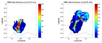
Figure 9 shows the snapshots with computed thickness for the HBM slide by using the model of a viscous fluid layer (Appendix B, with default parameter values). It flows downslope through the underlying canyon, and spreads eastwards when reaching the abyssal plain. The center of gravity follows closely the direction of the canyon, with an angle of 34o from the North. The computed time series for the velocity of the center of gravity appears in Figure 10 (curve VFH-1). It reaches a maximum value of 47.6 m/s after 12.7 minutes. It is worth noting that local velocities within the canyon surpasse 70 m/s, being lower at the flanks. When using the lower value for the density of sediments (1700 kg m−3), the maximum velocity of the center of gravity decreases to 42.5 m/s, and it occurs after 14 minutes.
The model of a viscous slide leads in this case to maximum velocities slightly lower than those obtained from the rigid block model. The initial acceleration is also lower, and the required time to reach the maximum speed is practically doubled. Two additional runs of the model will be considered by using the kinematics given by curves H-A1 and H-A2 in Figure 10. They fit the initial stage of the flow of the viscous slide and they account for a total run out of 65 km (again it is worth noting that the details of the last stage of the flow affect in a lesser extent to the generation of tsunami waves). Details are summarized in Table 1.
Model results
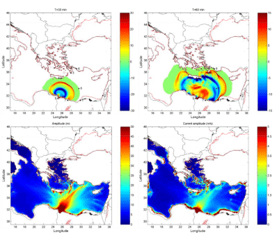
Results for HBM H3 are shown in Figure 11, and for HBM H-A2 in Figure S-5, in the electronic supplementary material. The dispersion pattern looks similar to the MTD-SL2 tsunami, but the proximity of the source area to the coastline and its extension, occupying most of the Gulf of Salˆum, makes difficult a faster filling of the depression formed at the rear of the slide. Most of the tsunami energy propagates northeast, reaching the southern coasts of the Hellenic Arc and Turkey with amplitudes over 40 m (data for H3). Amplitudes are also very high in the near field, along the coastline surrounding the source area. Extremely high currents with amplitudes over 15 m/s are found in the source area, and they exceed 10 m/s in most places of the northern coastlines of Libya and Egypt (data for H3).
Figure 12 shows the time series of computed water elevations at a set of selected locations (Figure 11). In this case the sites of Alexandria and Salˆum were initially emerged lands, but they undergo several flooding events with waves over 50 and 100 meters high, respectively. The site of Marsa Matruh is hit by waves over 50 m amplitude, and the receding of waters produces several events of complete desiccation. At south Rhodes, the tsunami amplitude exceeds 60 m, and it surpasses 18 m at Tel Aviv.
The peak energy of the HBM H3 tsunami is 6.0 × 10¹⁷ J (143 Megatons), which represents a conversion of 13.9% of the available potential gravitational energy in the prescribed motion (Table 1). The dispersion pattern of the HBM H-A2 tsunami (Figure S-5, in electronic supplementary material) results similar. Although it has a slower kine542 matics, its total run-out is longer, which results into a higher peak energy, of 6.8 × 10¹⁷ J (163 Megatons). This represents a more efficient conversion of ∼ 15.9% of the available gravitational potential energy. Similarly, for tsunami H-A1 the peak energy surpasses 180 Megatons.
Sensitivity tests show that the tsunami peak energy is primarily governed by the run out distance. A linear relationship holds with r2=0.996 and slope 3.76 Mt/km for the set of runs H0 to H6, since all of them share the same maximum velocity of the slide.
When including H-A1 and H-A2 the increasing trend still holds, but with a quadratic relationship (r2=0.982). Figures 13 and S-6 show the computed time series of water elevations for the whole set of simulated tsunamis (Table 1) at four selected locations. As the time of occurrence of maximum velocities for H0 to H6 vary only within two minutes (Figure S-4), there is not any noticeable shift in the arrival times. For H-A1 and H-A2, as the transfer of energy to the tsunami waves takes place over a longer time, the maximum computed water elevations at the selected locations, although with similar or slightly higher values than the rest of simulated tsunamis, appear delayed in time. At Alexandria (Figure 13) major changes are observed in the height of the second wave, with a maximum value around t = 100-110 minutes, being its amplitude clearly related to the tsunami peak energy. At South Rhodes, away from the direction of maximum energy propagation, tsunamis H3 to H5 (the most energetic ones within their set) produce some noticeable increase in the amplitude of the second receding wave, and with H-A1 the site of the tidal gauge becomes dry. In southern Crete and Fethije (Turkey), also away from the 563 direction of maximum energy propagation, all the tsunamis produce similar time series of water elevations, with few local disturbances that seem to be uncorrelated with their peak energy (Figure S-6).
Discussion
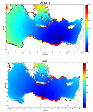
The MTD-SL2 tsunami, as modelled in run N0, produces runups over 30 m in the coasts around the source area, and at many places along the Hellenic Arc, SW Turkey and northern African coasts west of the source (Figure 14). Runups over 10 m occur at northern Crete and other areas of the Aegean Sea, around Cyprus, and along the Levantine and Libyan coasts. Runups over 4 m are registered in some coastal areas more than 1000 km away from the source, as in SE Italy.
The present set of modelling exercises shows that the MTD-SL2 event would have been able to release to the ocean water a peak energy two orders of magnitude higher than those of the Lisbon and the Indian Ocean tsunamis. The efficiency for the conversion of the gravitational energy would have been around 12% (mean value for the set of simulations). The propagation pattern shows strong directionality (northwestward directed), with major impacts registered in the North Africa coasts eastward of the source area and in southeastern Crete.
Concerning the Herodotus mass wasting event, the computed runups for H3 tsunami appear in Figure 14. The impacts are even stronger than those from MTD-SL2 tsunami, with runups over 30 m in most of the southern coasts of the Hellenic Arc and Turkey and northern Africa, from the Nile delta to the Gulf of Bumbah. It also produces runups over 10 m along the Gulf of Sirte, SE Italy and along the Greek shoreline.
Concerning the Herodotus mass wasting event, the computed runups for H3 tsunami appear in Figure 14. The impacts are even stronger than those from MTD-SL2 tsunami, with runups over 30 m in most of the southern coasts of the Hellenic Arc and Turkey and northern Africa, from the Nile delta to the Gulf of Bumbah. It also produces runups over 10 m along the Gulf of Sirte, SE Italy and along the Greek shoreline.
Figure 15 shows the computed time series of total tsunami energy (summation of gravitational potential and kinetic energies, given by Eq. 8 and 9) for a representative set of the studied tsunamis. The transfer of energy from the slide to the water column is a continuous (although not constant) process that finishes when the slide stops. Because of the coupling through friction, a fraction of the energy can pass back from water waves to the slide [47]. Energy dissipation through friction is always present and depends on the water depth and the instantaneous water current. Thus, dissipation is higher in shallow areas and close to the source (see maps of maximum current amplitudes in Figures 3,6,11). The tsunami peak energy occurs around the moment of maximum velocity or somewhat later. After the peak, energy decreases since dissipation becomes dominant. After the slide stops only dissipation governs the total energy. When the tsunami enters the deep sea, friction almost vanishes, and it increases again when reaching other continental shelves. The tsunami peak energy is primarily governed by the maximum velocity of the slide (as shown in the case of MTD-SL2 tsunamis) and, when this velocity is fixed, on the total run-out distance (as shown in the case of HBM tsunamis).
Thick slides moving downslope can reach relatively high velocities [25] and, thus, favor the transfer of energy to the ocean waters.
The efficiency in the conversion of gravitational energy into peak energy in the tsunami is about 3% for BIG’95, 12% for MTD-SL2, and around 17% for HBM tsunamis. This result suggests that blocks sliding in relatively shallow waters and within a gulf geometry (which makes difficult to fill up the depression formed at the rear of the slide) enhance the gravitational potential energy of the tsunami, and thus the global efficiency in energy conversion, which increases their harmful potential.
The total volume of seawater flooding the coastal areas can be estimated by multiplying the maximum water height at each flooded grid-cell by its surface. For MTD-SL2 this estimation leads to 270 ± 70 km3 (mean value and standard deviation) for the whole set of the eight runs. These flooding volumes are linearly correlated (r2 = 0.75) with the tsunami peak energy, as shown in Figure 16. For run N0, the flooding volume represents a 48% of the slide volume. When excluding coastal areas in the near field (operationally defined as those closer than 150 km from the slide front position) the same linear relationship still 623 holds (r2 = 0.67).
For HBM H-A1 tsunami, the most energetic one, the total volume of seawater flooding the coastal areas is 550 km3, being higher than the slide volume. For the whole set of HBM tsunamis the mean value and standard deviation are 383 ± 146 km3. The flooding volumes are also linearly correlated with the tsunami peak energy, as shown in Figure 16 (r2 = 0.90; and 0.87 when excluding the near field).
The acceleration of the sliding block can be estimated as the time derivative of its velocity (Eqs. 12 to .16). Its value for t = 0 (the initial acceleration) is a0 = 2Umax2 /R1; and it can be obtained from data in Table 1. The analysis of data for the whole set of MTD-SL2 and HBM tsunamis reveals a linear correlation at 95% confidence level (CL) among initial accelerations and the tsunami peak energy, but with a different trend for low and high values of a0. Thus, for a0 < 0.11 m s−2, the peak energy increases (r2 = 0.64), while it decreases for higher values of a0 (r2 = 0.55). The relationship with the total flooding volumes is weaker (90% CL). This distinct behavior also holds when using as independent variable the product of the total volume of the slide by its maximum velocity and by its initial acceleration [5], with a threshold value of ∼ 2.0 · 1012 m5 s−3.
Conclusion
A numerical model for tsunami propagation, based on the 2D depth-averaged nonlinear barotropic shallow water equations and allowing runup calculations, has been adapted to conduct an exploratory study on the tsunamigenic potential of some giant submarine landslides that occurred in the Mediterranean Sea during the Late Pleistocene. The model has been validated elsewhere for a wide set of tsunamis triggered by different mechanisms.
The 26 km3 debris flow BIG’95 scenario (at the Ebro continental slope, 11.5 ka BP) served for inter-comparison against independent modelling. The present modelling ap proach of a single Harbitz’s slide moving as a rigid body with a prescribed motion is able to account for the main tsunami features: propagation pattern, arrival times, maximum amplitude of water elevation and currents, and the overall tsunami energy.
Based upon the available geological studies, some source scenarios have been studied for the mass wasting events of MTD-SL2 (Nile delta) and HBM (Gulf of Salˆum) by using two alternative models: a rigid-block slide and a viscous flow layer. This served to estimate the kinematics of the slides, also subjected to a series of sensitivity tests.
The 500 km3 MTD-SL2 submarine landslide (110 ka BP, sea level 25 m below its present value) could have generated a tsunami with a peak energy two orders of magnitude higher than those of the Lisbon and the Indian Ocean Tsunamis. It would have impacted the Levantine Basin, the Central Mediterranean and the Southern Aegean Sea, with runups over 20 and 30 m and with water currents exceeding 10 m/s in some coastal areas.
The 300 km3 HBM tsunami (27 ka BP, -75 m msl) could have reached a peak energy over 140 Megatons. Most of the tsunami energy propagates towards northeast, reaching the southern coasts of the Hellenic Arc and Turkey, and northern Africa, from the Nile delta to the Gulf of Bumbah. Amplitudes are over 40 m and currents over 15 m/s at some locations. The total volume of water flooding the eastern Mediterranean coasts would have surpassed 380 km3 (mean value for the set of runs), with runups over 50 m in more than 1300 km2 of shoreline (data for H0).
The occurrence of thick submarine landslides at shallow depths, with high slope angles and within a gulf geometry, as the case of HBM, leads to the highest efficiency in energy conversion, and thus to the highest tsunami genic potentials.
The studied tsunamis occurred when the mean sea level was several tens of meters below its present value. Thus, despite the extremely high runups that they could have produced in the former coastal areas, the geological signatures that very likely left behind are presently submerged, and most likely masked by subsequent depositional or erosional processes. However, finding of some geological fingerprints cannot be discarded.
Although the used approach (slide as a rigid body with prescribed motion) is able to produce the main tsunami features, this work could be improved by carrying out a dynamic coupling between the slide model [27] model in which the slide is treated as a fluid layer forced by reduced gravity) and the tsunami propagation model.
Appendices
A) Kinematics for a rigid block slide
The slides start moving from rest, they reach a maximum velocity and then decelerates. For a single slope model, Harbitz [25] proposed a velocity at the slide front which is a sinusoidal function of time. The maximum velocity, Umax is estimated as a function of the slope angle, α, the average thickness of the slide, hm, its density, ρs (∼ 1.7 × 10³ kg m−3), the density of turbidity currents, ρt (∼ 1.1 × 10³ kg m−3), and the friction (µ) and drag (CDu ) coefficients [25]:
![]()
with CDu , the drag coefficient along the upper surface of the slide, being estimated from the roughness length parameter, k (in the range of 0.01 to 0.1 m):
![]()
The value of Umax strongly depends on the estimation of the Coulomb friction coefficient, µ, within an acceptable range (being its upper limit µst = tanα), and Umax must remain within the range of the reported values in scientific literature.
In many cases a first and large slope angle is involved in the triggering mechanism.
After a displacement R1 the slope angle decreases, but the moving masses still complete a second displacement R2. For each slope angle the maximum velocity Umax,1 and Umax,2 are estimated as commented above, and the following function of time is imposed:
![]()
with
![]()
and
![]()
with
![]()
where S(t) is the instantaneous position of the slide front at time t and
![]()
The “two slope angles” kinematics is a model choice, more general than the single sinus function used by Harbitz [25], but containing it as a particular case. The model also applies to cases with a single slope angle (Umax,1 = Umax,2); the specification of partial run-outs, R1 and R2, allows then generating asymmetric velocities profiles [28]. It is worth noting that the selected sinusoidal function requires four input (but non free) parameters: maximum velocities (governed by µ) and displacements. These last can be either estimated from geological studies, or introduced as plausible values subject to sensitivity tests. These displacements have to be understood as effective run-out distances (displacement of the sliding block), over which the transfer of energy to the tsunami takes place.
B) Governing equations for a viscous, incompressible fluid layer
The initial shape of the slide and its position on the source area are defined as in the Harbitz’s approach. The governing equations and the initial estimation for entry parameters have been adopted after Fine et al. [27]. Sediments in the slide have a density ρs(∼ 2.0 × 10³ kg m−3) and kinematic viscosity ν (∼ 0.01 m2 s−1) while the density of seawater is ρw(∼ 1.03 × 10³ kg m−3). Hs(x,y,t) is the local thickness of the slide at grid coordinates (x,y) and time t, and UA(x,y,t) is its vertically averaged horizontal velocity.
The seabed is designated by b(x,y). The wave effect on the slide movement is neglected. Conservation of mass and momentum for a viscous slide have the form [27]:
![]()
(18)
where c (∼ 0.0025) is the drag coefficient. The boundary conditions include that of no slide transport through the coastal boundary, and the assumption that the slide does not cross the open boundaries.
This research did not receive any specific grant from funding agencies in the public, commercial, or not-for-profit sectors. Authors thanks to the University of Seville for making available the working environment
- Abril JM, Peri´a˜nez R, Escacena JL (2013) Modeling tides and tsunami propagation in the former Gulf of Tartessos, as a tool for Archaeological Science. Journal of Archaeological Science 40: 4499-4508. Link: https://goo.gl/C1nh4c
- Kowalik Z, Knight W, Logan T, Whitmore P (2007) Numerical modelling of the Indian Ocean tsunami. In: Murty TS, Aswathanarayana U, Nipurama N (Eds.), The Indian Ocean Tsunami Taylor and Francis Group, London. 97-122. Link: https://goo.gl/kkyF0v
- Ruff LJ (2003) Some aspects of energy balance and tsunami generation by earth quakes and landslides. Pure and Applied Geophysics 160: 2155-2176. Link: https://goo.gl/tZNKXP
- Harbitz CB, Løvholt F, Bungum H (2014) Submarine landslide tsunamis: how extreme and how likely? Natural Hazards 72: 1341-1374. Link: https://goo.gl/QfDGvM
- Løvholt F, Harbitz CB, Haugen KB (2005) A parametric study of tsunamis generated by submarine slides in the Ormen Lange/Storegga area of western Norway. Marine and Petroleum Geology 22: 219-231. Link: https://goo.gl/P4v2sN
- Geist E, Lynett P (2014) Source Processes for the Probabilistic Assessment of Tsunami Hazards. Oceanography 27: 86-93. Link: https://goo.gl/7VINV5
- Papadopoulos GA, Gr`acia E, Urgeles R, Sallares V, De Martini PM, et al. (2014) Historical and pre-historical tsunamis in the Mediterranean and its connected seas: Geological signatures, generation mechanisms and coastal impacts. Marine Geology 354: 81–109. Link: https://goo.gl/Z0G8s4
- Urgeles R, Camerlenghi A (2013) Submarine landslides of the Mediterranean Sea: Trigger mechanisms, dynamics, and frequency-magnitude distribution. Journal of Geophysical Research: Earth Surface 118: 2600-2618. Link: https://goo.gl/OdH3ah
- Cita MB, Camerlenghi A, Rimoldi B (1996) Deep-sea tsunami deposits in the eastern Mediterranean: New evidence and depositional models. Sedimentary Geology 104: 155-173. Link: https://goo.gl/txZOia
- Cita MB, Rimoldi B (1997) Geological and geophysical evidence for the Holocene tsunami deposit in the eastern Mediterranean deep-sea record, Journal of Geodynamics 24: 293-304. Link: https://goo.gl/1ujPQR
- Hieke W, Werner F (2000) The Augias megaturbidite in the central Ionian Sea (central Mediterranean) and its relation to the Holocene Santorini event. Sedimentary Geology 135: 205-218. Link: https://goo.gl/Q4rD0n
- Shiki T, Cita B (2008) Tsunami-related sedimentary properties of Mediterranean homogenites as an example of deep-sea Tsunamiite. In: Tsunamiites and Implications (Shiki ET, Tsuji Y, Minoura K, Yamazaki T). Elsevier 203-215. Link: https://goo.gl/E2Fx45
- Peri´a˜nez R, Abril JM (2014) Modelling tsunamis in the Eastern Mediterranean Sea. Application to the Minoan Santorini tsunami storm, as a potential scenario 824 for the biblical Exodus. Journal of Marine Systems 139: 91-102. Link: https://goo.gl/QdKLvm
- Lastras G, Canals M, Hughes-Clarke JE, Moreno A, De Batist M, et al. (2002) Seafloor imagery from the BIG’95 debris flow, western 785 Mediterranean. Geology 10: 871-874. Link: https://goo.gl/h95Ks8
- Iglesias O, Lastras G, Canals M, Olabarrieta M, Gonz´alez M, et al. (2011) The BIG’95 submarine landslide-generated tsunami: A numerical 775 simulation. Journal of Geology 120: 31-48. Link: https://goo.gl/TC7uTg
- Rothwell RG, Thomson J, K¨ahler G (1998) Low-sea-level emplacement of a very large Late Pleistocene “megaturbidite” in the western Mediterranean Sea. Nature 392: 377-380. Link: https://goo.gl/ReNfRJ
- Droz L, dos Reis T, Rabineau M, Bern´e S, Bellaiche G (2006) Quaternary 744 turbidite systems on the northern margins of the Balearic Basin (Western Mediter745 ranean): a synthesis. Geo-Marine Letters 26: 347-359. Link: https://goo.gl/vekzcQ
- Rothwell RG, Reeder MS, Anastasakis G, Stow DAV, Thomson J, et al. (2000) Low sea-level stand emplacement of megaturbidites in the western and 842 eastern Mediterranean Sea. Sedimentary Geology 135: 75-88. Link: https://goo.gl/EbsQrb
- Reeder MS, Rothwell RG, Stow DAV (2000) Influence of sea level and basin physiography on emplacement of the late Pleistocene Herodotus Basin Megatur836 bidite, SE Mediterranean Sea. Marine and Petroleum Geology 17: 199-218. Link: https://goo.gl/kRXhyX
- Garziglia S, Migeon S, Ducassou E, Loncke L, Macle J (2008) Mass-transport deposits on the Rosetta province (NW Nile deep-sea turbidite system, Egyptian margin): Characteristics, distribution, and potential causal processes. Marine Geology 250: 180-198. Link: https://goo.gl/ovOblc
- Ten Brink US, Chaytor JD, Geist EL, Brothers DS, Andrews BD (2014) Assessment of tsunami hazard to the U.S. Atlantic margin. Marine Geology 353: 31-54. Link: https://goo.gl/5CQRfi
- De Blasio FV, Elverhøi A, Issler D, Harbitz CB, Bryn P, et al. (2004) Flow models of natural debris flows originating from overconsolidated clay materials. Marine Geology 213: 439-455. Link: https://goo.gl/pS3SBF
- Geist EL, Lynett PJ, Chaytor JD (2009) Hydrodynamic modeling of tsunamis from the Currituck landslide. Marine Geology 264: 41-52. Link: https://goo.gl/vRvB69
- Okal EA, Synolakis CE, Kalligeris N (2011) Tsunami Simulations for Regional Sources in the South China and Adjoining Seas. Pure Applied Geophysics 168: 1153-1173. Link: https://goo.gl/26pJqm
- Harbitz CB (1992) Model simulations of tsunamis generated by the Storegga slides. Marine Geology 105, 1-21. Link: https://goo.gl/hvV9cE
- Papadopoulos GA, Lobkovsky LI, Mazova RKh, Garagash IA, Karastathis V, et al. (2007) Numerical modeling of sediment mass sliding and tsunami generation: the case of February 7, 1963, in Corinth Gulf, Greece. Marine Geodesy 30: 315-331. Link: https://goo.gl/JQ3dzv
- Fine IV, Rabinovich AB, Bornhold BD, Thomson RE, Kulikov EA (2005) The Grand Banks landslide-generated tsunami of November 18, 1929: preliminary 748 analysis and numerical modeling. Marine Geology 215: 45-57. Link: https://goo.gl/KvHTL8
- Lastras G, De Blasio FV, Canals M, Elverhøi A (2005) Conceptual and numerical modeling of the BIG’95 debris flow, western Mediterranean Sea. Journal of Sedimentary Research 75: 784-797. Link: https://goo.gl/RMW6Uz
- Løvholt F, Harbitz CB, Vanneste M, De Blasio FV, Urgeles R, et al. (2014) Modeling Potential Tsunami Generation by the BIG’95 Landslide, Submarine Mass Movements and Their Consequences. Advances in Natural and Technological Hazards Research 37: 507-515 Link: https://goo.gl/7frsdh
- Ward SN (2001) Landslide Tsunami. Journal of Geophysical Research 106: 11201-11215. Link: https://goo.gl/hzhyZt
- Glimsdal S, Pedersen GK, Harbitz CB, Løvholt F (2013) Dispersion of tsunamis: does it really matter? Natura Hazards and Earth System Science 13: 1507-1526. Link: https://goo.gl/LpIQ9g
- Bondevik S, Løvholt F, Harbitz C, Mangerud J, Dawson A, et al. (2005) The Storegga Slide tsunami: comparing field observations with numerical simulations. Marine and Petroleum Geology 22: 195-208. Link: https://goo.gl/2x2DJA
- Harbitz CB, Løvholt F, Pedersen G, Masson DG (2006) Mechanisms of 763 tsunami generation by submarine landslides: a short review. Norwegian Journal of Geology 86: 255-264. Link: https://goo.gl/Puiy88
- Peri´a˜nez R, Abril JM (2013) Modelling tsunami propagation in the Iberia-Africa plate boundary: historical events, regional exposure and the case-study of the former Gulf of Tartessos. Journal of Marine Systems 111: 223-234. Link: https://goo.gl/DwPYj0
- Peri´a˜nez R, Abril JM (2014) a numerical modelling study on oceanographic conditions in the former Gulf of Tartessos (SW Iberia): Tides and tsunami propa827 gation. Journal of Marine Systems 139: 68-78. Link: https://goo.gl/GGAr79
- Pillans B, Chappell J, Nash TR (1998) a review of the Milankovitch climatic beat: template for Plio-Pleistocene sea-level changes and sequence stratigraphy. Sedimentary Geology 122: 5-21. Link: https://goo.gl/WrdFrW
- L´opez-Venegas AM, Ten Brink US, Geist EL (2008) Submarine landslide as the source for the October 11, 1918 Mona Passage tsunami: Observations and modeling. Marine Geology 254: 35-46. Link: https://goo.gl/wXyAsc
- Tappin DR, Watts P, Grilli ST (2008) The Papua New Guinea tsunami of 17 July 1998: anatomy of a catastrophic event. Natural Hazards and Earth System Sciences 8: 243-266. Link: https://goo.gl/ZDnGD0
- De Blasio FV, Elverhøi A, Issler D, Harbitz CB, Bryn P, et al. (2005) On 741 the dynamics of subaqueous clay rich gravity mass flows -the giant Storegga slide, Norway. Marine and Petroleum Geology 22: 179-186. Link: https://goo.gl/kZwzTO
- Kowalik Z, Murty TS (1993) Numerical Modelling of Ocean Dynamics. World Scientific 481. Link: https://goo.gl/LG84cC
- Tinti S, Pagnoni G, Zaniboni F (2006) The landslides and tsunamis of the 30th of December 2002 in Stromboli analyzed through numerical simulations. Bulletin of Volcanology 68: 462-479. Link: https://goo.gl/Ow9Ccj
- Herzfeld M, Schmidt M, Griffies SM, Liang Z (2011) Realistic test cases for limited area ocean modelling. Ocean Modelling 37:1-34. Link: https://goo.gl/xAc73L
- Kampf J (2009) Ocean Modelling for Beginners. Springer-Verlag, Heidelberg 175. Link: https://goo.gl/svxKFt
- Peri´a˜nez R, Abril JM (2015) Computational fluid dynamics simulations of the Zanclean catastrophic flood of the Mediterranean (5.33 Ma). Palaeogeography, Palaeoclimatology, Palaeoecology 424: 49-60. Link: https://goo.gl/MmPyG3
- Loncke L Gaullier V, Macle J, Vendeville B, Camera L (2006) The Nile deep-sea fan: An example of interacting sedimentation, salt tectonics, and inherited subsalt paleotopographic features. Marine Geology 23: 297-315. Link: https://goo.gl/pq0gE6
- Loncke L, Vendeville BC, Gaullier V, Mascle J (2010) Respective contributions of tectonic and gravity - driven processes on the structural pattern in the Eastern Nile deep-sea fan: insights from physical experiments. Basin Research 22: 765-782. Link: https://goo.gl/UqBP2I
- Tinti S, Bortolucci E, Chiavettieri C (2001) Tsunami excitation by submarine 856 slides in shallow water approximation. Pure and Applied Geophysics 158: 759-797. Link: https://goo.gl/4LVJ1Q
Article Alerts
Subscribe to our articles alerts and stay tuned.
 This work is licensed under a Creative Commons Attribution 4.0 International License.




 Save to Mendeley
